| Author |
Message |
Mark_A_W
Joined: 15 Mar 2006
Posts: 3068
Location: Sunny Melbourne Australia
|
| Posted: Sun Apr 18, 2010 2:22 am Post subject: |
|
|
I don't know what to make of that without pictures, other than we need the whole number, including Inkstamp.
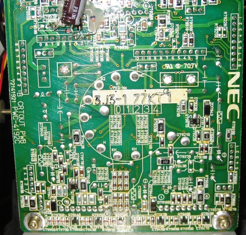
And that the 1101 number looks wrong to me - my 1101 has 72141921 PWC-4192B Inkstamp 3J3 neckboards (see images above).
|
|
| Back to top |
|
 |
Ironman1965
Joined: 28 Jun 2007
Posts: 98
|
| Posted: Sun Apr 18, 2010 3:31 am Post subject: |
|
|
Well thanks Jerry. Looks like you and I have the same guts in our 1350's. I agree with you Mark. I think I'll mod this puppy before I close this patient up. What do you suggest for a grounding location. There are many locations on the board. This would be closest to the original resistor's location. Do you figure this will be OK?
Red - Cut Traces
Blue - 3M9 Ohm 1/2 Watt Resistor
Black - Jumpers
http://i154.photobucket.com/albums/s254/Ironman1965/CRT/P4150027d.jpg
|
|
| Back to top |
|
|
jarseneau

Joined: 06 Nov 2007
Posts: 323
Location: WI
|
| Posted: Sun Apr 18, 2010 6:26 am Post subject: |
|
|
| Mark_A_W wrote: | I don't know what to make of that without pictures, other than we need the whole number, including Inkstamp.
And that the 1101 number looks wrong to me - my 1101 has 72141921 PWC-4192B Inkstamp 3J3 neckboards (see images above). |
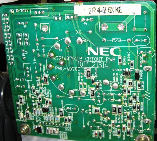
Mark, my mistake about the 1101. The correct numbers are ..921.
| Description: |
|
| Filesize: |
221.64 KB |
| Viewed: |
4948 Time(s) |
|
| Description: |
|
| Filesize: |
199.71 KB |
| Viewed: |
4948 Time(s) |
|
_________________
Jerry
|
|
| Back to top |
|
|
Mark_A_W
Joined: 15 Mar 2006
Posts: 3068
Location: Sunny Melbourne Australia
|
| Posted: Sun Apr 18, 2010 7:06 am Post subject: |
|
|
|
Yep, looking at that last image, of a 1st gen neckboard for an 06/07 tube, you need to mod the neckboard.
|
|
| Back to top |
|
|
Ironman1965
Joined: 28 Jun 2007
Posts: 98
|
| Posted: Sun Apr 18, 2010 11:10 am Post subject: |
|
|
| Mark_A_W wrote: | Yes, I agree, the schematic is for your board.
We've always known the schematic didn't match the stock neckboard, but now I have seen a neckboard that it does match.
I would do the mod as I drew it, except perhaps to a better ground location. Having the board images helps.
I would NOT just hook up an 06/07 tube and hope for the best.
It will be interesting to see what Jerry comes up with - whether his XGs have different neckboards. I suspect you can "get away" with putting an 08 in the 07 neckboard, but not the reverse (hence the sticker).
Mark |
Wouldn't you know! I was right in the middle of replying to this post and  .....blackness..... the freaking power goes out. Anyway as I was about to say a few hours ago. Those engineers over at NEC must have been psychic when they designed this board. They must have known that one day 14 years in the future that some character like myself was going to start cutting traces on their precious boards. Luckily I've dabbled in hacking electronics before (with mixed results I might add .....blackness..... the freaking power goes out. Anyway as I was about to say a few hours ago. Those engineers over at NEC must have been psychic when they designed this board. They must have known that one day 14 years in the future that some character like myself was going to start cutting traces on their precious boards. Luckily I've dabbled in hacking electronics before (with mixed results I might add  ) and gotten into the habit of continuity testing all cut traces. I cut the trace from G1 to R7938, did my standard continuity test and..... Beeeeeep! "You've got connection". What?! So I double check the precision of my skilled cut. Looks good. So I flip the board over and what do I find but a redundant trace on the component side of the board. Well, no mad scientist worth his salt is going to leave any redundant organs in his monster, so good old doctor Freakenstein performs one more tracectomy on his beautiful creation. Hmwa ha ha ha ha! Oh oh! I think this little project of mine has driven the old Ironman to madness ) and gotten into the habit of continuity testing all cut traces. I cut the trace from G1 to R7938, did my standard continuity test and..... Beeeeeep! "You've got connection". What?! So I double check the precision of my skilled cut. Looks good. So I flip the board over and what do I find but a redundant trace on the component side of the board. Well, no mad scientist worth his salt is going to leave any redundant organs in his monster, so good old doctor Freakenstein performs one more tracectomy on his beautiful creation. Hmwa ha ha ha ha! Oh oh! I think this little project of mine has driven the old Ironman to madness  ! All stuff aside though. With that redundant trace from G1 to R7938, I did have some concern that NEC may have been foolhardy enough to actually hide a trace from the lower G1 to the upper G1 behind the tube socket, which would have just made soooo much more work for me, but after I cut that trace and did the continuity test, my trusty Fluke gave me the all clear sound of silence ! All stuff aside though. With that redundant trace from G1 to R7938, I did have some concern that NEC may have been foolhardy enough to actually hide a trace from the lower G1 to the upper G1 behind the tube socket, which would have just made soooo much more work for me, but after I cut that trace and did the continuity test, my trusty Fluke gave me the all clear sound of silence  . BTW, anybody know if these nuclear power cells they put in the Fluke meters ever die. Mine have been just going and going and going since 1992 leaving a big black boot print on the old Energizer Bunnies back side. I can't believe that I haven't replaced them yet. Too bad all batteries don't last this long. Good thing I lost my sleep gland in that horrific accident when I was but a stripling. The good deeds a person can accomplish with only 2 hour sleep per night. It's a totally superior uber-power when compared to the lame crap that blue guy on The Watchmen uses. As with any uber-power though, there comes great responsibility. Mine is the consumption of copious amounts of.... "the java bean" . BTW, anybody know if these nuclear power cells they put in the Fluke meters ever die. Mine have been just going and going and going since 1992 leaving a big black boot print on the old Energizer Bunnies back side. I can't believe that I haven't replaced them yet. Too bad all batteries don't last this long. Good thing I lost my sleep gland in that horrific accident when I was but a stripling. The good deeds a person can accomplish with only 2 hour sleep per night. It's a totally superior uber-power when compared to the lame crap that blue guy on The Watchmen uses. As with any uber-power though, there comes great responsibility. Mine is the consumption of copious amounts of.... "the java bean"  . Anyway Mark, back on topic, what location would you suggest for ground? Here's my idea (grounds the resistor nearest to the factory location for R7946, not that it really matters, nice and close though). What do you think? . Anyway Mark, back on topic, what location would you suggest for ground? Here's my idea (grounds the resistor nearest to the factory location for R7946, not that it really matters, nice and close though). What do you think?
Red - Cut Traces
Blue - Resistor 3M9 Ohm 1/2 Watt
Black - Jumpers
http://i154.photobucket.com/albums/s254/Ironman1965/CRT/P4150027d.jpg
Cheers, and thank you everyone for all the help and feedback. You are all AWESOME! 
Ray.
|
|
| Back to top |
|
|
Mark_A_W
Joined: 15 Mar 2006
Posts: 3068
Location: Sunny Melbourne Australia
|
| Posted: Sun Apr 18, 2010 12:19 pm Post subject: |
|
|
Looks good to me.
You have the board, not me. I dunno if that's ground or not.
The only reason I picked the back of the ground lead pins, was I knew that was ground for sure.
|
|
| Back to top |
|
|
Ironman1965
Joined: 28 Jun 2007
Posts: 98
|
| Posted: Sun Apr 18, 2010 3:37 pm Post subject: |
|
|
|
Mark, if I used the pin on POTG for ground that ground routes through R7941 47 Ohm 1/2 W then C7915 .01uf 250VCK. With my limited knowledge of electronics I'm assuming the resistor and cap are for protection? Would it be better to use that spot or the one in my image which is direct to ground.
|
|
| Back to top |
|
|
Ironman1965
Joined: 28 Jun 2007
Posts: 98
|
| Posted: Sun Apr 18, 2010 3:42 pm Post subject: |
|
|
|
Why is there so much more "stuff" on those other boards?
|
|
| Back to top |
|
|
Mark_A_W
Joined: 15 Mar 2006
Posts: 3068
Location: Sunny Melbourne Australia
|
| Posted: Sun Apr 18, 2010 9:36 pm Post subject: |
|
|
| Ironman1965 wrote: | | Mark, if I used the pin on POTG for ground that ground routes through R7941 47 Ohm 1/2 W then C7915 .01uf 250VCK. With my limited knowledge of electronics I'm assuming the resistor and cap are for protection? Would it be better to use that spot or the one in my image which is direct to ground. |
I think direct to ground.
|
|
| Back to top |
|
|
Mark_A_W
Joined: 15 Mar 2006
Posts: 3068
Location: Sunny Melbourne Australia
|
| Posted: Sun Apr 18, 2010 9:38 pm Post subject: |
|
|
| Ironman1965 wrote: | | Why is there so much more "stuff" on those other boards? |
The later generation XGs have a push-pull neckboard with a pair of video output amps.
This, along with the LC, is the biggest change over the original.
|
|
| Back to top |
|
|
Ironman1965
Joined: 28 Jun 2007
Posts: 98
|
| Posted: Sun Apr 18, 2010 11:20 pm Post subject: |
|
|
|
My mistake Mark. Disregard my post regarding ground. I was looking at the schematic backwards. I think I've just been looking at this stuff too long. Thanks. I'll let you all know how it works out. I just need to wait to get the 3M9's.
|
|
| Back to top |
|
|
|
|