| Author |
Message |
Nashou66

Joined: 12 Jan 2007
Posts: 16171
Location: West Seneca NY
|
| Posted: Mon Aug 09, 2010 5:55 pm Post subject: |
|
|
| dvh99 wrote: | yeah that is one cool picture there scott.
jarmo too bad your holiday has finished i hope you had a great time, where did you spend your holiday, italy spain greek islands?
i will defenitely try that ths3201 even if it takes me 20 decoupling caps  . .
as for the transistor/mosfet i have been searching some more on the www and i found this
http://www.semiconductor-sanyo.com/ds_e/ENN3179A.pdf
if anyone has some suggestions for a replacement for the 2n3906 please let me know because i am still on the lookout.
the 2n3906 is a limiting factor and i do not want that. |
Look trough my maintenance thread. its in there some where, not in my main works but in discussions between Jarmo and I.
It was something like a BRF93 or something
Atrhanasios
_________________
Don't blame your underwear for your crooked ass~ unknown Greek philosopher
"Republicans believe every day is the Fourth of July, but the Democrats believe every day is April 15." --- President Reagan
One Smart Dog!!!
Marquee High Performance Bellows now shipping!!
Marquee Modifications and Performance Enhancement
Marquee C-element and Bellow removal
|
|
| Back to top |
|
 |
dvh99

Joined: 25 Dec 2009
Posts: 2158
Location: nederland
|
| Posted: Mon Aug 09, 2010 6:00 pm Post subject: |
|
|
thanks nash i will look at that later, now i am off playing some soccer  . .
_________________
1 answer always poses multiple questions.
marquee 9500ultra HD10L moome hdmi1.3 v3+ some mods.
|
|
| Back to top |
|
|
tse
Joined: 03 May 2006
Posts: 1014
Location: Sweatbucket, Fl.
|
| Posted: Mon Aug 09, 2010 8:36 pm Post subject: |
|
|
http://www.fairchildsemi.com/ds/MP/MPSH81.pdf
might work ok.
I used the 2N3906 on that proto board and had good results.
Scott
_________________
"Were we directed from Washington when to sow and when to reap, we would soon want bread."
Thomas Jefferson
|
|
| Back to top |
|
|
dvh99
Joined: 25 Dec 2009
Posts: 2158
Location: nederland
|
| Posted: Mon Aug 09, 2010 9:19 pm Post subject: |
|
|
http://nl.farnell.com/nxp/bfr93/transistor-npn-rf-sot-23/dp/1081298?Ntt=bfr93
you mean this one nash? i want those they were manufactured here at philips .
scott i am looking for something with a higher bandwidth then 250mhz.
what was the idea behind developing a vim with the ad834, the ad835 was good enough for most installations and still is.
_________________
1 answer always poses multiple questions.
marquee 9500ultra HD10L moome hdmi1.3 v3+ some mods.
|
|
| Back to top |
|
|
Nashou66
Joined: 12 Jan 2007
Posts: 16171
Location: West Seneca NY
|
| Posted: Mon Aug 09, 2010 11:16 pm Post subject: |
|
|
| dvh99 wrote: | http://nl.farnell.com/nxp/bfr93/transistor-npn-rf-sot-23/dp/1081298?Ntt=bfr93
you mean this one nash? i want those they were manufactured here at philips .
scott i am looking for something with a higher bandwidth then 250mhz.
what was the idea behind developing a vim with the ad834, the ad835 was good enough for most installations and still is. |
Yep those, they have a p and and n version so make sure you get the right ones.
Athanasios
_________________
Don't blame your underwear for your crooked ass~ unknown Greek philosopher
"Republicans believe every day is the Fourth of July, but the Democrats believe every day is April 15." --- President Reagan
One Smart Dog!!!
Marquee High Performance Bellows now shipping!!
Marquee Modifications and Performance Enhancement
Marquee C-element and Bellow removal
|
|
| Back to top |
|
|
tse
Joined: 03 May 2006
Posts: 1014
Location: Sweatbucket, Fl.
|
| Posted: Mon Aug 09, 2010 11:59 pm Post subject: |
|
|
| dvh99 wrote: |
scott i am looking for something with a higher bandwidth then 250mhz.
what was the idea behind developing a vim with the ad834, the ad835 was good enough for most installations and still is. |
A customer wanted a 5 mega pixel display. 2560 x 2048 @ 60Hz. Pixel clock about 400MHz. So I made a video system with flat BW out to 200MHz but only about 60Vpp cathode drive. Lexel made a low drive CRT and it worked. It would resolve one pixel on/one pixel off test patterns. Once everyone realised that the Marquee chassis wasn't up to it (coarse convergence) and figured the cost of the custom CRTs and new power supply the project kinda just died. Bummer.
Scott
_________________
"Were we directed from Washington when to sow and when to reap, we would soon want bread."
Thomas Jefferson
|
|
| Back to top |
|
|
1031

Joined: 22 Mar 2006
Posts: 657
Location: Finland
|
| Posted: Tue Aug 10, 2010 7:57 am Post subject: |
|
|
| dvh99 wrote: | yeah that is one cool picture there scott.
jarmo too bad your holiday has finished i hope you had a great time, where did you spend your holiday, italy spain greek islands?
i will defenitely try that ths3201 even if it takes me 20 decoupling caps .
as for the transistor/mosfet i have been searching some more on the www and i found this
http://www.semiconductor-sanyo.com/ds_e/ENN3179A.pdf
if anyone has some suggestions for a replacement for the 2n3906 please let me know because i am still on the lookout.
the 2n3906 is a limiting factor and i do not want that. |
Well my vacation was pretty "domestic" Lapland, Neste Oil rally.. etc..
I suggest that you start with original parts CLC449, 2n3906 etc.. you are asking for troubles if you are trying to to "all mods" at the same time. Been there, done that 
Those 2n3906 are not limithing Bw much, that kind (not remember what was that circuit called.. cascoid amplifier.. something) circuit works over specced bandwhidth.
_________________
Marquee 9500LC (Frankenyokes / Thomas electric tubes / HD-10L / +many mod´s)
DVDO VP-50
New hobby, Rally
http://www.youtube.com/watch?v=vX2Rtpr1njs
http://www.youtube.com/watch?v=6ZP9FEFXV5c
http://www.youtube.com/watch?v=j065vei6j6s
http://www.facebook.com/pages/JTS-Racing-team/204443719572685
|
|
| Back to top |
|
|
dvh99
Joined: 25 Dec 2009
Posts: 2158
Location: nederland
|
| Posted: Tue Aug 10, 2010 1:07 pm Post subject: |
|
|
jarmo the clc449 is not available anymore, i will order the el5166 too but i like the ths3201 to work.
farnell also has special rf caps that i will try on the ths3201 to see how that works maybe 5 in parallel.
how does the 2n3906 perform with pixelclocks above 300 mhz?
about the convergence scott, it isnt the best but it certainly isnt bad, from viewing distance i cannot see any convergence errors.
i will change out the tl071`s and the tl084`s with tle2071 and tle2074 to see if that helps there too.
_________________
1 answer always poses multiple questions.
marquee 9500ultra HD10L moome hdmi1.3 v3+ some mods.
|
|
| Back to top |
|
|
tse
Joined: 03 May 2006
Posts: 1014
Location: Sweatbucket, Fl.
|
| Posted: Tue Aug 10, 2010 6:06 pm Post subject: |
|
|
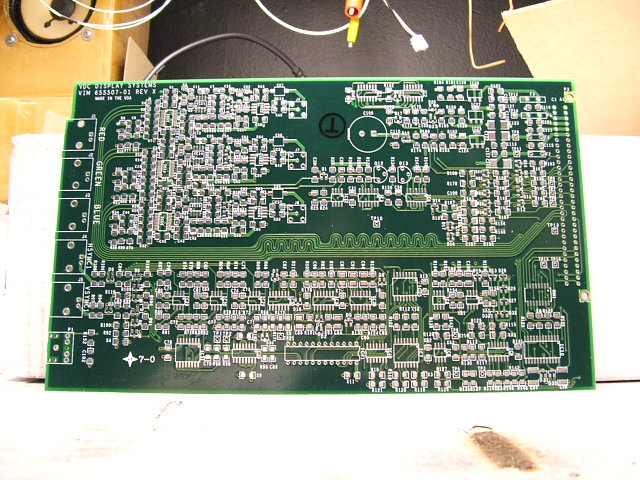
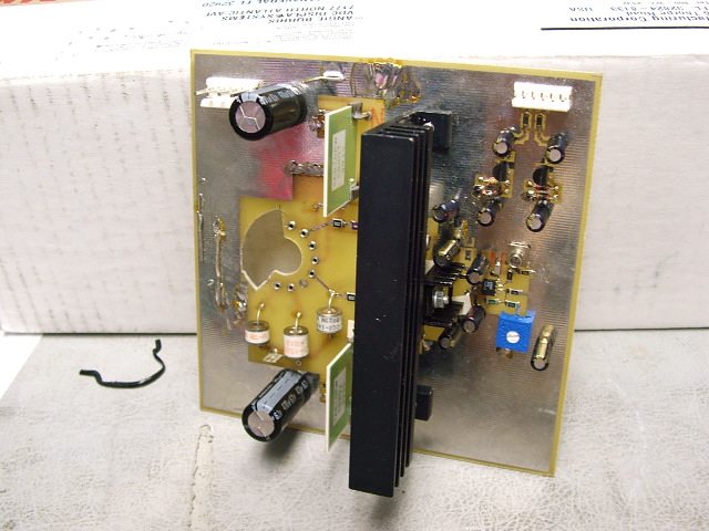
This kinda goes with the original topic. A VDC VIM that never happened. A couple of PCBs were made then the project was abandoned. A pic of the 200MHz neck card prototype.
Scott
| Description: |
|
| Filesize: |
127.69 KB |
| Viewed: |
10537 Time(s) |
|
| Description: |
|
| Filesize: |
117.33 KB |
| Viewed: |
10537 Time(s) |
|
_________________
"Were we directed from Washington when to sow and when to reap, we would soon want bread."
Thomas Jefferson
|
|
| Back to top |
|
|
Nashou66
Joined: 12 Jan 2007
Posts: 16171
Location: West Seneca NY
|
|
| Back to top |
|
|
Sparky015

Joined: 12 May 2009
Posts: 1185
Location: Cleveland / Akron, OH
|
| Posted: Tue Aug 10, 2010 6:54 pm Post subject: |
|
|
| Nashou66 wrote: | Scott, I always wondered about the wavy trace lines on some circuit boards. What is their purpose?
Athanasios |
You want the lengths to be the same to keep things in phase. Since the layout prohibits this, they made the two shorter lengths wavy in order to get them equal the longest one. Wen your dealing with the mHz level (especially 200), trace lengths come into play.
_________________
~Paul
|
|
| Back to top |
|
|
dvh99
Joined: 25 Dec 2009
Posts: 2158
Location: nederland
|
| Posted: Tue Aug 10, 2010 9:54 pm Post subject: |
|
|
i see the prototype had the smb connectors why were they not used instead of the mini rca.
the smb connector with the 4 legs is also commonly available.
_________________
1 answer always poses multiple questions.
marquee 9500ultra HD10L moome hdmi1.3 v3+ some mods.
|
|
| Back to top |
|
|
dvh99
Joined: 25 Dec 2009
Posts: 2158
Location: nederland
|
| Posted: Wed Aug 11, 2010 5:52 pm Post subject: |
|
|
simple question here, is the vim a 3-layer board?
i wonder what is better, getting the contrast signal straight from the opamp mc34084 which i will replace btw or getting them from the testpoints near the rca connectors.
_________________
1 answer always poses multiple questions.
marquee 9500ultra HD10L moome hdmi1.3 v3+ some mods.
|
|
| Back to top |
|
|
dvh99
Joined: 25 Dec 2009
Posts: 2158
Location: nederland
|
| Posted: Fri Aug 13, 2010 7:21 pm Post subject: |
|
|
pic of the vim addon pcb

plus backside, i will order 1 board next week plus all components.

Last edited by dvh99 on Sun Aug 15, 2010 3:17 pm; edited 1 time in total
|
|
| Back to top |
|
|
dvh99
Joined: 25 Dec 2009
Posts: 2158
Location: nederland
|
| Posted: Sat Aug 14, 2010 4:01 pm Post subject: |
|
|
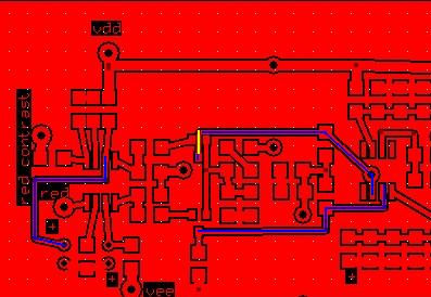
as you can see on the layout the vdd and vee voltages are connected.
is it better to get rid of them and feed 3*vee plus vdd to the ad834 chips.
or leave them and still feed 3*vee plus vdd to the ad834 chips.
_________________
1 answer always poses multiple questions.
marquee 9500ultra HD10L moome hdmi1.3 v3+ some mods.
|
|
| Back to top |
|
|
dvh99
Joined: 25 Dec 2009
Posts: 2158
Location: nederland
|
| Posted: Sat Aug 14, 2010 10:21 pm Post subject: |
|
|
1 more question, in the schedule of the 03p vim a diode lies on "digital ground", but doing a continuity test from "analog ground" to "digital ground" it says resistance 0.
this confuses me and i need to know what the difference between the groundplanes is cause next week all components will arrive and i will start with the board when the pcb is made.
_________________
1 answer always poses multiple questions.
marquee 9500ultra HD10L moome hdmi1.3 v3+ some mods.
|
|
| Back to top |
|
|
tse
Joined: 03 May 2006
Posts: 1014
Location: Sweatbucket, Fl.
|
| Posted: Sun Aug 15, 2010 5:30 pm Post subject: |
|
|
I see you have been working on the PCB layout. It does look better. A couple of things that I noticed, might not be a problem, I've shown on the attached pic. The blue lines are kinda long. HF traces can never be too short. A PCB trace can be 1nH/mm. A 20mm trace at 200MHz can be a significant impedance. The yellow line looks like there might be some clearance issue. Cheap bd houses usually want more than 7 mils.
The schematic from the app note shows 1uF decoupling caps on the multiplier. I don't know of any 1uF caps that have low impedance at 200MHz. I have had good luck with 1000pF COG or NPO type ceramic caps right at the IC power leads with short traces to ground plane. A larger cap a little further away if necessary.
Don't worry about analog and digital ground here. Everything is going to be analog ground. They do have to connect together somewhere perferably somewhere where there are no large high frequency currents.
Scott
| Description: |
|
| Filesize: |
25.31 KB |
| Viewed: |
10303 Time(s) |
|
_________________
"Were we directed from Washington when to sow and when to reap, we would soon want bread."
Thomas Jefferson
|
|
| Back to top |
|
|
dvh99
Joined: 25 Dec 2009
Posts: 2158
Location: nederland
|
| Posted: Sun Aug 15, 2010 8:12 pm Post subject: |
|
|
thanks scott for your explanation, the clearance is only shown on the picture but not on the print from the layout.
the pcb is 11*12cm so it will fit nicely on the vim.
the guy who will be making the pcb`s offers an option to add a silver layer to the entire pcb, i read that is a good thing in hf circuits.
i have shortened the blue line on the left with a trace that goes underneath.
i could make the blue lines coming from the transistor wider if that helps lowering impedance
the holes for the connectors are for the smb connectors.
http://www.farnell.com/datasheets/55118.pdf
in the layout you can see 2 holes on the + and -, those are for the 1uf oscons i want to use, do you think placing a 1000pf cap, in parallel with the oscon, from the link would improve things?
dennis
|
|
| Back to top |
|
|
tse
Joined: 03 May 2006
Posts: 1014
Location: Sweatbucket, Fl.
|
| Posted: Sun Aug 15, 2010 9:54 pm Post subject: |
|
|
The silver is probably a good thing but you shouldn't have to go to the expense. I've done alot of HF bds with only one ounce copper (two ounce is more standard) tinned plating and they have been ok.
I do believe that impedance is determined by length and width with L / W = Z. So wider does decrease Z.
http://www.kemet.com/kemet/web/homepage/kechome.nsf/weben/kemsoft
Very informative free Spice program that shows the impedance of various caps vs frequency. Above a cap's resonant frequency it will actually become inductive. Not what you want decoupling the power rails on HF opamps.
Placing a 1000pF COG ceramic right on pin 6 of the multipier with the other end directly to ground plane would be optimum. The way it is now there is a fairly long trace between pin 6 and the decoupling cap. Undesired inductance in series with cap lowers resonant frequency. I can't say it won't work but why not make it as good as possible?
Scott
_________________
"Were we directed from Washington when to sow and when to reap, we would soon want bread."
Thomas Jefferson
|
|
| Back to top |
|
|
dvh99
Joined: 25 Dec 2009
Posts: 2158
Location: nederland
|
| Posted: Sun Aug 15, 2010 11:11 pm Post subject: |
|
|
you are absolutely right, i will make the trace wider and i have shortened the trace already it now goes straight to the ad834.
should i leave the oscon there and add the cog ceramic or replace the oscon with a cog ceramic.
_________________
1 answer always poses multiple questions.
marquee 9500ultra HD10L moome hdmi1.3 v3+ some mods.
|
|
| Back to top |
|
|
|
|