| Author |
Message |
draganm
Joined: 08 Mar 2006
Posts: 8990
Location: Colorado
|
| Posted: Fri Dec 11, 2009 4:13 am Post subject: |
|
|
| Nashou66 wrote: | then I looked at the cables coming out of the back heat sink boards. on all marquees from before they were all separated. These are braided tightly together. I have a feeling that its that.
Athanasios |
I haven't had a chance to follow this thread but that's really wierd?You simply don't that with wires, ever.
If you look through some of the oplder TCB's from E-home Canada there's a couple tha talk about the routing of those wires specifically in relation to noise in the image.
|
|
| Back to top |
|
 |
Nashou66

Joined: 12 Jan 2007
Posts: 16171
Location: West Seneca NY
|
| Posted: Fri Dec 11, 2009 4:39 am Post subject: |
|
|
I guess for certain types of signals it be ok, like audio and the braided Kimber Kable. However that is just one cable to one speaker. you would never braid the left and right speakers together. here they braided the CVA,VDM, and SAB wires all in one braided bundle. Once un braided the lighter bars reduced to the point they are no longer in the viewed image at normal contrast. However at lower contrast like 20 loooking into the tube the lines are there but now all the same width and intensity. Like Mike said these most likely come from the IPG on the CLM and are always there in the background but not enough to be noticeable.
My Theory is the excessive noise from the SAB wires might have amplified and Carry those background lines to the point of visibility in the image on screen.
But VDC really needs to look into a redesign of the SAB, with out the ferrite cable clamp i can not use it. The weird thing Drag, is that only one ferrite clamp was all that was needed to clear up al channels. I wish someone could explain how that can be, I looked at the schematic and all channels are separate except for the power lines. But one clamp only cleans up one line, why would all other lines not feed more noise into the amps again and cause the same thing. i was expecting just the one channel i put the clamp on to improve not all. I only have two of that type so i could not test what effect all three would have.
I did test the outputs for the cva and VDM with the same clamps and they do not have the same noise , just much smaller higher frequency noise . other means would be need for that.
Also scoping the video lines did not show this noise i saw on the screen , this proves to me that noise in the image can be introduced through other means than just the video path. The Astig coils themselves were putting noise, well the proper term should be distortions over the video image. these squiggles were not affected by any geometry control and were alway in the same location, unless i changed the internal frequencies. I am glad i found it was the SAB as i was beginning to think there was some kind of defect of the tubes.
Athanasios
_________________
Don't blame your underwear for your crooked ass~ unknown Greek philosopher
"Republicans believe every day is the Fourth of July, but the Democrats believe every day is April 15." --- President Reagan
One Smart Dog!!!
Marquee High Performance Bellows now shipping!!
Marquee Modifications and Performance Enhancement
Marquee C-element and Bellow removal
|
|
| Back to top |
|
|
Nashou66
Joined: 12 Jan 2007
Posts: 16171
Location: West Seneca NY
|
| Posted: Tue Dec 22, 2009 5:56 am Post subject: |
|
|
I began doing the same things to my second longbow , but after i still had the lighter bars. the ferrite cleared up the squggles great.
So i began removing boards and cleaned the chips on the CLM.
Then I decided to remove the CMM, sure enough that is the problem. That board too might be oscillating. i have the newest boards so i dont have the schematic.
But i will try a few things on it. Damn bran new PJ's and all sorts of problems!!!
Athanasios
_________________
Don't blame your underwear for your crooked ass~ unknown Greek philosopher
"Republicans believe every day is the Fourth of July, but the Democrats believe every day is April 15." --- President Reagan
One Smart Dog!!!
Marquee High Performance Bellows now shipping!!
Marquee Modifications and Performance Enhancement
Marquee C-element and Bellow removal
Last edited by Nashou66 on Tue Dec 22, 2009 3:31 pm; edited 1 time in total
|
|
| Back to top |
|
|
AnalogRocks
Forum Moderator
Joined: 08 Mar 2006
Posts: 26706
Location: Toronto, Ontario, Canada
TV/Projector: Sony 1252Q, AMPRO 4000G
|
| Posted: Tue Dec 22, 2009 6:00 am Post subject: |
|
|
| Nashou66 wrote: | t. Damn bran new PJ's and all sorts of problems!!!
Athanasios |
Poor you 
_________________
Tech support for nothing
CRT.
HD done right!
|
|
| Back to top |
|
|
Nashou66
Joined: 12 Jan 2007
Posts: 16171
Location: West Seneca NY
|
| Posted: Fri Dec 25, 2009 6:25 pm Post subject: |
|
|
Well another Problem solved!!!! Thanks Scott for the Schematics. here is what i had to do.
I first looked up the data sheets for the Op amp that runs the zone correction, its a Analog Devices OP249GS. I first wanted to use the OPA2134 and tried it but then realized the DIP and SOIC have different pin locations!!! Oopps!!!
So i went to put the original back and reversed it, in a hurry haste makes waste guys, and I blew that channel(blue) so i decided to order a new one and still tackle the issue on the green channel.
I first added a 220uh inductor on the output of the G-Corr. that helped a little, so i looked over the data sheets some more and found an example that looks very similar to the CCM layout.
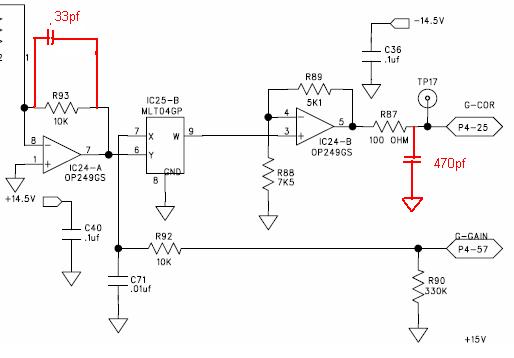
Well the way these are configured on the CCM is in a bipolar configuration , in the data sheet they suggest a 33pf capacitor on the first stage feedback. I did not have any that value but i do have tons of 100pf silver mica caps.
I added one and it really helped!! then I added another to get the value as close the 33pf so two 100pf in parallel
make 50pf. Now the brighter three or four vertical lines are gone!!!
Data sheet diagram, this is different pin layout than the CCM's but it workes the same, also the CCM has an extra chip
stage between the two OP249 stages, that is for the Gain.

here is a diagram of what i did on the Green channel, i found it easier to add the caps on the under side across the resistor.
So once I get the other chip and replace it i'll do the same for the other channels.
EDIT: Thanks Jarmo for catching my mistake, I changed the parallel 100pf caps to three in series to get the 33pf value.
But I Am going to order 33pf caps.

Athanasios
_________________
Don't blame your underwear for your crooked ass~ unknown Greek philosopher
"Republicans believe every day is the Fourth of July, but the Democrats believe every day is April 15." --- President Reagan
One Smart Dog!!!
Marquee High Performance Bellows now shipping!!
Marquee Modifications and Performance Enhancement
Marquee C-element and Bellow removal
Last edited by Nashou66 on Tue Jan 12, 2010 4:01 am; edited 2 times in total
|
|
| Back to top |
|
|
HK-Steve

Joined: 15 Jul 2006
Posts: 849
Location: Switzerland
TV/Projector: Marquee 9500, Epson 8100
|
| Posted: Fri Dec 25, 2009 6:52 pm Post subject: |
|
|
Hmmm, Interesting that, that solved part of the problem.
I would be interested to see the schematics, I saw a couple of improvements over the original design,
but also a couple of issues that were not an improvement.
Schematics would really let me see why issues were not solved.
Glad you saw an improvement, more work still to do.
Cheers
Steve
|
|
| Back to top |
|
|
1031
Joined: 22 Mar 2006
Posts: 657
Location: Finland
|
|
| Back to top |
|
|
Nashou66
Joined: 12 Jan 2007
Posts: 16171
Location: West Seneca NY
|
|
| Back to top |
|
|
1031
Joined: 22 Mar 2006
Posts: 657
Location: Finland
|
|
| Back to top |
|
|
Nashou66
Joined: 12 Jan 2007
Posts: 16171
Location: West Seneca NY
|
| Posted: Fri Dec 25, 2009 7:22 pm Post subject: |
|
|
| HK-Steve wrote: | Hmmm, Interesting that, that solved part of the problem.
I would be interested to see the schematics, I saw a couple of improvements over the original design,
but also a couple of issues that were not an improvement.
Schematics would really let me see why issues were not solved.
Glad you saw an improvement, more work still to do.
Cheers
Steve |
your right, Scott said the adjustments are much better
but the problem is hard to fix, he wished me luck in trying to
solve it!! Guess I got it. Although I did not test all zones in green
so not 100% sure. The two zones I tried worked so I asume the others
will also. On my iPhone now at my parents, then x-mass at my sis's. So it won't be
till midnight I'll look at it more.
Nashou
_________________
Don't blame your underwear for your crooked ass~ unknown Greek philosopher
"Republicans believe every day is the Fourth of July, but the Democrats believe every day is April 15." --- President Reagan
One Smart Dog!!!
Marquee High Performance Bellows now shipping!!
Marquee Modifications and Performance Enhancement
Marquee C-element and Bellow removal
|
|
| Back to top |
|
|
Nashou66
Joined: 12 Jan 2007
Posts: 16171
Location: West Seneca NY
|
| Posted: Fri Dec 25, 2009 9:12 pm Post subject: |
|
|
Ok had some time before i go to my sisters, put three 100pf silver micas together to make 33.3pf cap and I got Much better results!! then I added 10uf Os-Cons on top of the 100nf power supply Ceramic caps and it got even a little better. This board is just as noisy as the Astig board. now I know why MP suggests you remove it if not needed.
Athanasios
_________________
Don't blame your underwear for your crooked ass~ unknown Greek philosopher
"Republicans believe every day is the Fourth of July, but the Democrats believe every day is April 15." --- President Reagan
One Smart Dog!!!
Marquee High Performance Bellows now shipping!!
Marquee Modifications and Performance Enhancement
Marquee C-element and Bellow removal
|
|
| Back to top |
|
|
tse
Joined: 03 May 2006
Posts: 1014
Location: Sweatbucket, Fl.
|
| Posted: Sat Dec 26, 2009 6:41 pm Post subject: |
|
|
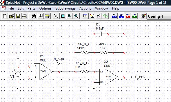
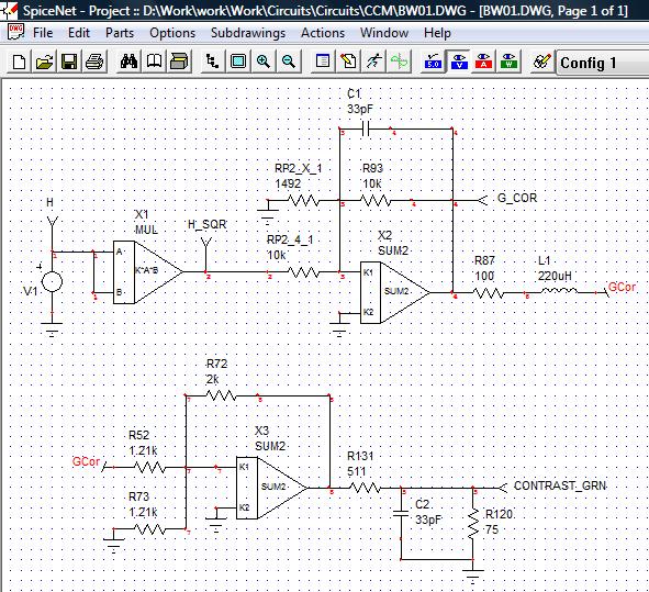
You have to be careful when adding filters for noise that you don't also filter your signal. Attached is a simplified circuit of part of the CCM. The signal being simulated is the right side modulation. The right half of a horizontal freq ramp is input. That is squared to get the proper right side parabola and applied to the inverting output stage. You want that signal to maintain fidelity through the rest of the circuits. Adding 33pF doesn't look too bad only changing the signal a small amount. With 200pF across R93 you have a signal that is much different from the original.
Scott
| Description: |
|
| Filesize: |
70.17 KB |
| Viewed: |
7481 Time(s) |
|
| Description: |
|
| Filesize: |
23.57 KB |
| Viewed: |
7481 Time(s) |
|
| Description: |
|
| Filesize: |
24.01 KB |
| Viewed: |
7481 Time(s) |
|
| Description: |
|
| Filesize: |
24.14 KB |
| Viewed: |
7481 Time(s) |
|
_________________
"Were we directed from Washington when to sow and when to reap, we would soon want bread."
Thomas Jefferson
|
|
| Back to top |
|
|
Nashou66
Joined: 12 Jan 2007
Posts: 16171
Location: West Seneca NY
|
| Posted: Sat Dec 26, 2009 8:17 pm Post subject: |
|
|
Thanks for the Info Scott. I only am adding the 33pf to the G-Cor in the very last stage of the CCM, i am not going to change the H-Sqr or the other signals on the CMM unless that stage is similar to the one from the data sheets, a bi polar layout.
One other thing, I first used the 220uh inductor then the caps, can you add the inductor into the spice program and see what the results are, that is if its needed or not. Now looking back its hard to tell visually if its helping at all.
I did notice one thing here are the details, I have the right PJ with no CMM in it right now, and the other I have the Blue channel not working(blown OP249 i think) and the correction caps on the green and the red is left alone for now, but when i start both PJ's up for the blend they have perfect convergence from a cold start and even after they warm up. Can the CMM's affect convergence till the PJ warms up or could this just be a weird coincidence?
Also if you leave the setting for zone contrast at 0 and scope the corr signal it has lots and lots of noise and it also bounces the trace. After the cap was added the noise was lowered but still a lot but the bouncing remains but is a little less with the inductor, any ideas about that?
Athanasios
_________________
Don't blame your underwear for your crooked ass~ unknown Greek philosopher
"Republicans believe every day is the Fourth of July, but the Democrats believe every day is April 15." --- President Reagan
One Smart Dog!!!
Marquee High Performance Bellows now shipping!!
Marquee Modifications and Performance Enhancement
Marquee C-element and Bellow removal
|
|
| Back to top |
|
|
tse
Joined: 03 May 2006
Posts: 1014
Location: Sweatbucket, Fl.
|
| Posted: Sun Dec 27, 2009 12:03 am Post subject: |
|
|
Circuit with VIM section added. You can see some filter action with the 220uH in series with the g-cor signal. Even with both 220uH and 33pF the filtering isn't horribly excessive. This is at 68kHz. Might be too much at 150kHz.
Scott
| Description: |
|
| Filesize: |
107.54 KB |
| Viewed: |
7448 Time(s) |
|
| Description: |
|
| Filesize: |
23.61 KB |
| Viewed: |
7448 Time(s) |
|
| Description: |
|
| Filesize: |
25.98 KB |
| Viewed: |
7448 Time(s) |
|
_________________
"Were we directed from Washington when to sow and when to reap, we would soon want bread."
Thomas Jefferson
|
|
| Back to top |
|
|
Nashou66
Joined: 12 Jan 2007
Posts: 16171
Location: West Seneca NY
|
| Posted: Sun Dec 27, 2009 12:27 am Post subject: |
|
|
Thanks Scott, I did see the same waves on the scope while adding Adjustment, the waves also change depending on which way from 0 you go up or down. However they are not as clean as your spice model , they are full of noise spikes. the filters clean it up a bit but like your model's scope the amplitude does get lowered a bit.At no adjustment where the Corr signal is suppose to be flat there are small bumps after adding the filters, before they were larger and more of them. As long as I see the lines in the image gone i'll leave it as is. i wish i knew a bit more on using the spice program. which one are you using? i know a few of the Chip makers have free programs for download, i tried with the one from Ti i think but never fully understood it.
Athanasios
_________________
Don't blame your underwear for your crooked ass~ unknown Greek philosopher
"Republicans believe every day is the Fourth of July, but the Democrats believe every day is April 15." --- President Reagan
One Smart Dog!!!
Marquee High Performance Bellows now shipping!!
Marquee Modifications and Performance Enhancement
Marquee C-element and Bellow removal
|
|
| Back to top |
|
|
Nashou66
Joined: 12 Jan 2007
Posts: 16171
Location: West Seneca NY
|
| Posted: Wed Feb 10, 2010 3:10 pm Post subject: |
|
|
I Did some more testing and found I could totally eliminate the bars with a cap to ground from the X-COR output.

I tried 470pf first and it worked great but only had 100pf and smaller values to also test and those did not work as well or at all.
I will try a 220 PF EMI filter, it has a center tap that goes to ground and the cap would go across resistor R87.
Id like Scott to run that through his Spice program if possible. I wish I knew how to use that thing and wish they made a MAC OSX version somewhere.
I'll try to post some pics of the before and after wave form, there is a ripple in the signal but on screen it looks good, not sure what that ripple is doing to the image or signal.
Athanasios
| Description: |
|
| Filesize: |
21.3 KB |
| Viewed: |
7366 Time(s) |
|
_________________
Don't blame your underwear for your crooked ass~ unknown Greek philosopher
"Republicans believe every day is the Fourth of July, but the Democrats believe every day is April 15." --- President Reagan
One Smart Dog!!!
Marquee High Performance Bellows now shipping!!
Marquee Modifications and Performance Enhancement
Marquee C-element and Bellow removal
|
|
| Back to top |
|
|
cmjohnson

Joined: 03 Apr 2006
Posts: 5180
Location: Buried under G90s
|
| Posted: Wed Feb 10, 2010 9:11 pm Post subject: |
|
|
Do the bars move when you use different internal test frequencies?
CJ
|
|
| Back to top |
|
|
Nashou66
Joined: 12 Jan 2007
Posts: 16171
Location: West Seneca NY
|
|
| Back to top |
|
|
Nashou66
Joined: 12 Jan 2007
Posts: 16171
Location: West Seneca NY
|
| Posted: Thu Feb 18, 2010 3:33 am Post subject: |
|
|
Well I got the bars to go away but there is still noise on the Cor signal and the inductor/cap combination
creates a little bump in the wave form. but from what i can tell looking at the grey scale/ and full field internal patterns its not causing any image issues and the zone adjustments seem to work ok. I wont know for sure how ell it will al work till i use it in the blend and look at video.
I tried the 470pf to ground and 220uh in series with the cor signal and got this wave form.

Wave form with 20mhz Bandwidth limit off, not sure what i need to do to clean this up, i tried lots of filtering of the power lines I should try an inductor in series to each pin, what value would you suggest to get it looking as it does with the 20mhz BW/L on.

Now how it looks with the 220uh/220pf combo, this works well i think, but still noise with BW/L off.

BW/L off

I tried 120pf as well but the bars showed up and the bump inthe trace was like the
470pf, odd I think.
One more thing I looked at though I scoped the cor signal before the in series 220uh inductor and the bump was gone. But I know if I remove that inductor the bars come back in the image, i need both inductor and cap together for the bars to be gone.
Athanasios
_________________
Don't blame your underwear for your crooked ass~ unknown Greek philosopher
"Republicans believe every day is the Fourth of July, but the Democrats believe every day is April 15." --- President Reagan
One Smart Dog!!!
Marquee High Performance Bellows now shipping!!
Marquee Modifications and Performance Enhancement
Marquee C-element and Bellow removal
|
|
| Back to top |
|
|
draganm
Joined: 08 Mar 2006
Posts: 8990
Location: Colorado
|
| Posted: Sat Feb 27, 2010 10:53 pm Post subject: |
|
|
| Nashou66 wrote: | Thanks Craig, looks like the moving of wires helped. But the issue is still there for oscillation on the SAB board Like TSE stated. I noticed they use a new chip the EL2245 and its a 100Mhz chip and that seems like the noise getting through.
I am pretty sure i seen a SAB board with the MC3402 chip which is much less. I am at work now so have to look.
Steve and I were talking and He thinks he used the TLE2072 chip there. I have some at home and might try it. But i have to wait for his confirmation. Not sure what bandwidth requirements are needed for the astig adjustment but i don not think its a high bandwidth need, unless its dependent on the refresh rate your running,
EDIT: Ok just got home and the older boards have the same chip. Maybe Steve was mistaken, have to wait and see.
Athanasios |
Any confirmation on a replacement for the EL2245CN? I'm not looking to hot-rod this board, simply looking to repair a SAB channel and the EL2245CN is no longer available? 
|
|
| Back to top |
|
|
|
|