| Author |
Message |
lexx21
Joined: 10 Oct 2008
Posts: 119
|
| Posted: Tue Nov 24, 2009 1:50 am Post subject: 6pgxtra question |
|
|
|
I have a pg6200 that I am starting to setup. The raster on all 3 tubes is bowed at the top and bottom (inward). The pj is setup for front floor use. Can someone give me any ideas as to how to solve this?
|
|
| Back to top |
|
 |
Curt Palme
CRT Tech
Joined: 08 Mar 2006
Posts: 24396
Location: Langley, BC
TV/Projector: All of them!
|
| Posted: Tue Nov 24, 2009 1:58 am Post subject: |
|
|
I'll answer once you get rid of that sick avatar 
It could be partly normal, otherwise the convergence output connectors on the C board are backwards. Flip each one of the 6 around 180 degrees, and plug back in. That should give you proper convergence control. There should be a sticker inside the main lid showing the orientation of the connectors. To be clear, they are the yellow/brown and red/blue ones on the C board, 6 in total.
|
|
| Back to top |
|
|
lexx21
Joined: 10 Oct 2008
Posts: 119
|
| Posted: Tue Nov 24, 2009 5:16 am Post subject: |
|
|
No appreciation for the hairy hedgehog eh?
Ok, when you are changing around the jumpers, on the deflection board the color code is meant to be read when you are facing (lens pointing to you) the projector? And on the C board when you are looking at the pj from the rear (lens facing away from you)? Looking at the drawing inside the cover that's what it seems to be saying.
Basically the left and right side are fine, it's the top and bottom that are bowed toward the middle and wasn't something that I could adjust out. I reseated all of the connectors on the C board and that didn't solve it. I'm probably overlooking something really obvious.
|
|
| Back to top |
|
|
benareeno
Joined: 22 Mar 2006
Posts: 1614
Location: ottawa, canada
|
| Posted: Tue Nov 24, 2009 6:49 am Post subject: |
|
|
|
it's the orientation of those plugs...one way or another, it's the plugs.
|
|
| Back to top |
|
|
Elaine Benes
Joined: 25 Apr 2006
Posts: 1416
|
| Posted: Tue Nov 24, 2009 11:10 pm Post subject: |
|
|
There's also the plugs UNDER the main deflection board that all need to be oriented properly AND located on the correct pins....
Check the manual.
The pins are labelled, and the color orientation and plug orientation are detailed in relation to the pins in the manual....
|
|
| Back to top |
|
|
lexx21
Joined: 10 Oct 2008
Posts: 119
|
| Posted: Sun Nov 29, 2009 3:41 am Post subject: |
|
|
Well, I tried all of the combinations of plug orientations on both the C board and the deflection board and I still can't seem to get rid of the inward bowing of the raster top and bottom. The sides are correct though. Any other ideas?
Also shouldn't all three crt's be on on power up with no input? Right now there are only the green and the blue. When I start a grid test pattern on the set (internal patterns) all three light up. Just wondering.
|
|
| Back to top |
|
|
benareeno
Joined: 22 Mar 2006
Posts: 1614
Location: ottawa, canada
|
| Posted: Sun Nov 29, 2009 5:30 am Post subject: |
|
|
have you deleted all memories? Then normalized all values? Or reset defaults?
A factory reset may be in order...many will warn that your house will blow up. But I've done them on every NEC I've had and it's often worthwhile for reasons like this.
|
|
| Back to top |
|
|
Curt Palme
CRT Tech
Joined: 08 Mar 2006
Posts: 24396
Location: Langley, BC
TV/Projector: All of them!
|
| Posted: Sun Nov 29, 2009 5:36 am Post subject: |
|
|
Don't worry about what tubes are on or off without a signal
The connectors you want to change are the yellow and brown ones on the C board under the deflection board. make sure a signal is fed to the projector, the set will do strange things without one.
|
|
| Back to top |
|
|
lexx21
Joined: 10 Oct 2008
Posts: 119
|
| Posted: Mon Dec 14, 2009 3:47 pm Post subject: |
|
|
|
I used a transcanner for the rgbhv input, cleared all memories on the pj, set everything to null, and still have have the same issue. I have played with the plugs on the C board and sweep board in every combination that I can think of and still no change. The top and bottom are still bowed inward.
|
|
| Back to top |
|
|
benareeno
Joined: 22 Mar 2006
Posts: 1614
Location: ottawa, canada
|
| Posted: Mon Dec 14, 2009 4:34 pm Post subject: |
|
|
|
take a pic of it and share...
|
|
| Back to top |
|
|
lexx21
Joined: 10 Oct 2008
Posts: 119
|
| Posted: Mon Dec 14, 2009 7:49 pm Post subject: |
|
|
|
Will do....it wil likely be Wednesday before I can do that, but I will definitely take pics.
|
|
| Back to top |
|
|
benareeno
Joined: 22 Mar 2006
Posts: 1614
Location: ottawa, canada
|
| Posted: Mon Dec 14, 2009 8:00 pm Post subject: |
|
|
|
take a pic of the tube face and a pic of the plugs on and under the deflection board.
|
|
| Back to top |
|
|
Mark_A_W
Joined: 15 Mar 2006
Posts: 3068
Location: Sunny Melbourne Australia
|
| Posted: Mon Dec 14, 2009 10:23 pm Post subject: |
|
|
With the correct plug setup, the raster will still be bowed when the alignment/convergence controls are zero'd.
That's what the alignment/convergence controls are for....
If you don't have enough adjustment, you have an issue, but otherwise it's normal.
|
|
| Back to top |
|
|
lexx21
Joined: 10 Oct 2008
Posts: 119
|
| Posted: Tue Dec 15, 2009 1:45 am Post subject: |
|
|
That's the problem though... I can adjust it out on the sides, but not top and bottom. Top and bottom don't even move. I can see correct video (nothing scrambled) when I pull up the menu on the transcanner. I followed the chart for the plug color code and set it to desktop/front.
I will take pics of the C board plugs and sweep board plugs so you can see what I have.
|
|
| Back to top |
|
|
lexx21
Joined: 10 Oct 2008
Posts: 119
|
| Posted: Sat Dec 19, 2009 10:16 pm Post subject: |
|
|
I swapped the brown/yellow orientation on the C board as Curt suggested. Still the same issue with the top and bottom of each color being bowed inward and not adjusting outward.
I guess that I should also add that I used the dwin transcanner as a source input while trying to make the adjustments. I'm pretty confused here about what to do next.
|
|
| Back to top |
|
|
Elaine Benes
Joined: 25 Apr 2006
Posts: 1416
|
| Posted: Sun Dec 20, 2009 10:19 pm Post subject: |
|
|
| lexx21 wrote: | I swapped the brown/yellow orientation on the C board as Curt suggested. Still the same issue with the top and bottom of each color being bowed inward and not adjusting outward.
I guess that I should also add that I used the dwin transcanner as a source input while trying to make the adjustments. I'm pretty confused here about what to do next. |
Start by posting those pictures you said you were going to...
Everyone here with NEC experience says its the plug orientation, but there isn't any evidence without those pictures to confirm your plugs ARE indeed oriented correctly. Until we can absolutely eliminate that as the cause, there's no way to help you further...
|
|
| Back to top |
|
|
lexx21
Joined: 10 Oct 2008
Posts: 119
|
| Posted: Tue Dec 22, 2009 12:22 am Post subject: |
|
|
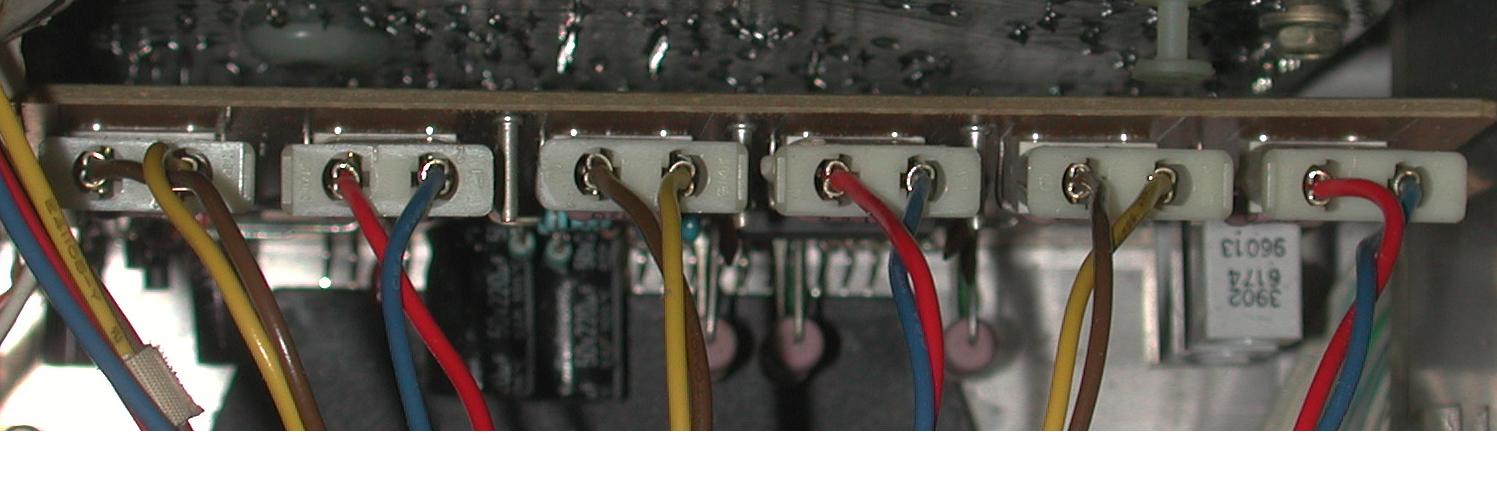
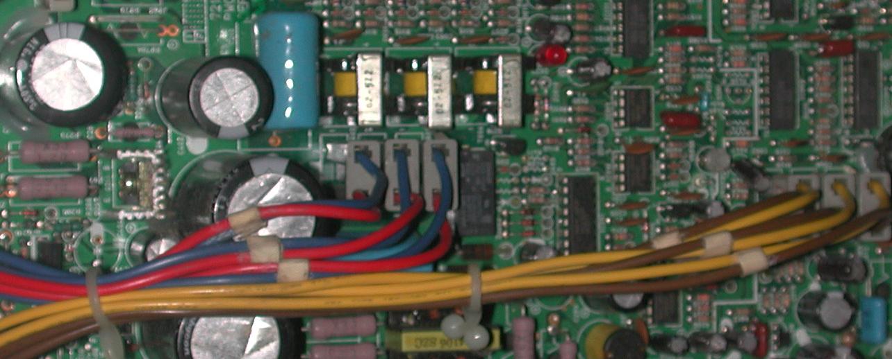
Ok, here are the pics of the boards. My camera is a pos and I can't get it to change shutter speeds from 1/60 sec, so it picks up only the raster scan and no the whole image on he tube face....ugh!
Describing what is on the tube face.... when I go into a menu, I can read it just fine. The top and bottom are bowed inward. It also does this on the test paterns and affects those patterns since they use the whole area that you have set for your raster.
I tried the plug combination (C board) that was on the label on the inside lid for front desktop. I did it using the component side as a reference and also the back of the board as a reference (left to right reading the colors). The way that it is drawn in the diagram, it seems to be with the back of the projector as the reference so I wasn't sure about that.
I saw in a post that curt replied to over on AVS where he told a guy to reverse the yellow/brown on the C board which is what I have done here in the pics that I posted but I am still having the same issue.
I'm seriously hoping that I don't have a bad board and that it's just a matter of "operator head space" here.
| Description: |
|
| Filesize: |
80.28 KB |
| Viewed: |
7121 Time(s) |
|
| Description: |
|
| Filesize: |
92.28 KB |
| Viewed: |
7115 Time(s) |
|
|
|
| Back to top |
|
|
Elaine Benes
Joined: 25 Apr 2006
Posts: 1416
|
| Posted: Tue Dec 22, 2009 2:50 am Post subject: |
|
|
Funny how things work out, eh ?
I just yesterday evening sold my PG Xtra that has been in the garage for over a year...otherwise, I'd just head out there now with a printout of your plug orientation picture to confirm them...Hopefully someone else who still has an Xtra in their possession can confirm your orientation. Sorry...
Just some more info, you *should* be able to confirm your plug orientation is correct by looking directly on the board that they plug into, there is both the actual designation for each plug eg. AG, BG, etc, and the pin number printed right on the board so you can get the orientation unquestionably correct.
|
|
| Back to top |
|
|
lexx21
Joined: 10 Oct 2008
Posts: 119
|
| Posted: Mon Dec 28, 2009 12:59 am Post subject: |
|
|
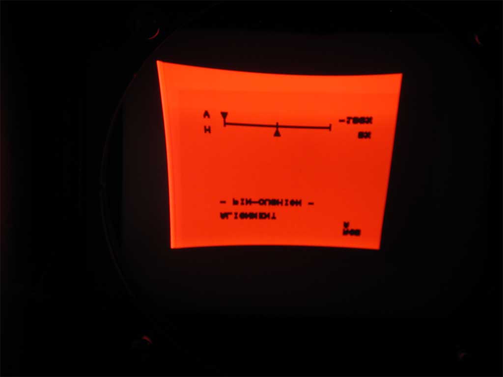
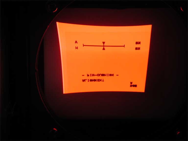
I figured out what you were talking about concerning the orientation and now have it correct. The brown/yellow on the C board were backward. I corrected that but still have the same issue with top/bottom bowing. I have pics of the screen faces that I will need to get off of the camera and will upload them asap. I can move the vertical pin cushion to either extreme and still no movement to remove the bowing of any of the tube faces?
Horizontal movement works perfectly.
Would I start looking at the stk pack at the bottom of the C board next? As long as the part is available, replacing the part isn't really an issue for me if that is the most likely suspect in this case.
Below are the pics that I took of the red crt face (all other crt faces looked the same). As you can see, no change once the vertical pin cushion is changed.
| Description: |
|
| Filesize: |
14.69 KB |
| Viewed: |
8348 Time(s) |
|
| Description: |
|
| Filesize: |
12.77 KB |
| Viewed: |
8348 Time(s) |
|
|
|
| Back to top |
|
|
Elaine Benes
Joined: 25 Apr 2006
Posts: 1416
|
| Posted: Mon Dec 28, 2009 7:33 am Post subject: |
|
|
Yes, starting off by replacing the STK392-040 chips is the usual tack, I think, I had to do it on one PG I had long ago ....
Got the chips from some place in Georgia...mmmm...Georgia Audio Labs maybe ?
|
|
| Back to top |
|
|
|
|


