| Author |
Message |
Arno P

Joined: 01 Jan 2007
Posts: 282
Location: The Netherlands
|
| Posted: Thu Aug 28, 2008 4:39 pm Post subject: |
|
|
In case a neckboard, tube and LVPS are ok....what needs to be connected for the HV to power up (or does it only power up if 3 neckboards/tubes are connected?
_________________
"Obviously you're not a golfer"
|
|
| Back to top |
|
 |
Curt Palme
CRT Tech
Joined: 08 Mar 2006
Posts: 24396
Location: Langley, BC
TV/Projector: All of them!
|
| Posted: Thu Aug 28, 2008 5:18 pm Post subject: |
|
|
I can repair it, or to save time, sell you one, you send me back the old one.
Power the set up with only the two G and B neck boards connected, those two tubes should work fine.
If sparks fly out of the back of the red tube with no neck board on it, then the red tube has a crack in it. I doubt that's the case, I'll bet it is a simple neck board failure.
|
|
| Back to top |
|
|
Arno P
Joined: 01 Jan 2007
Posts: 282
Location: The Netherlands
|
| Posted: Thu Aug 28, 2008 5:23 pm Post subject: |
|
|
| Curt Palme wrote: | I can repair it, or to save time, sell you one, you send me back the old one.
Power the set up with only the two G and B neck boards connected, those two tubes should work fine.
If sparks fly out of the back of the red tube with no neck board on it, then the red tube has a crack in it. I doubt that's the case, I'll bet it is a simple neck board failure. |
Ok, so at this moment the pj is stripped from all the boards, connecting the G/B neckboard and powering up should also switch the HV on (without HDM etc. in place)? Or should everything be back except the Red neckboard to make this possible?
_________________
"Obviously you're not a golfer"
|
|
| Back to top |
|
|
Curt Palme
CRT Tech
Joined: 08 Mar 2006
Posts: 24396
Location: Langley, BC
TV/Projector: All of them!
|
| Posted: Thu Aug 28, 2008 5:27 pm Post subject: |
|
|
|
Put everything back in place save for the red neck board.
|
|
| Back to top |
|
|
Arno P
Joined: 01 Jan 2007
Posts: 282
Location: The Netherlands
|
| Posted: Thu Aug 28, 2008 5:43 pm Post subject: |
|
|
| Curt Palme wrote: | | Put everything back in place save for the red neck board. |
Ok, let's rewind the disassembly and see how many screws will be left 
_________________
"Obviously you're not a golfer"
|
|
| Back to top |
|
|
Arno P
Joined: 01 Jan 2007
Posts: 282
Location: The Netherlands
|
| Posted: Thu Aug 28, 2008 6:25 pm Post subject: |
|
|
I have put back all the boards except the red neckboarc...the pj seems to power up...clack click...filament on the tubes glow...and a H-fail LED on the back glows  ...or is this caused by the diconnected neckboard? ...or is this caused by the diconnected neckboard?
Also....no glowing CRT....so HV jet? Any checks I can do?
Edit: Found it, needed to connect the RED HDM Connector as well and after that the B and G were alive again...
Last check I will do is apply video signal and swop the Green neckboard to red to see if it still works..
_________________
"Obviously you're not a golfer"
|
|
| Back to top |
|
|
Curt Palme
CRT Tech
Joined: 08 Mar 2006
Posts: 24396
Location: Langley, BC
TV/Projector: All of them!
|
| Posted: Thu Aug 28, 2008 6:54 pm Post subject: |
|
|
|
THere ya go. email me at curtpalme@shaw.ca for a new neckboard.
|
|
| Back to top |
|
|
Arno P
Joined: 01 Jan 2007
Posts: 282
Location: The Netherlands
|
| Posted: Fri Aug 29, 2008 8:16 am Post subject: |
|
|
WE GOT HIM...! 
I connected the ground of the defect and a good neckboard to the ground of the multimeter and started comparing with the diagram of the neckboard in front of me.
Passive measurement, tricky since the multimeter will charge capacitors...and that voltage might open certain transistors....and then the comparitive measurement between the boards doesn't make sense.
(Second option would be to connect reduced voltages to both boards with a safe current limit on the supply and actively comparing voltages).
But, I did it the passive way yesterday and I expected some transistors suffering from the "measurement voltage/charge" of the meter....so I let it rest a night and continued this morning paying attention to shortly put the probes on the pcb limiting the charge that would be injected to the components.
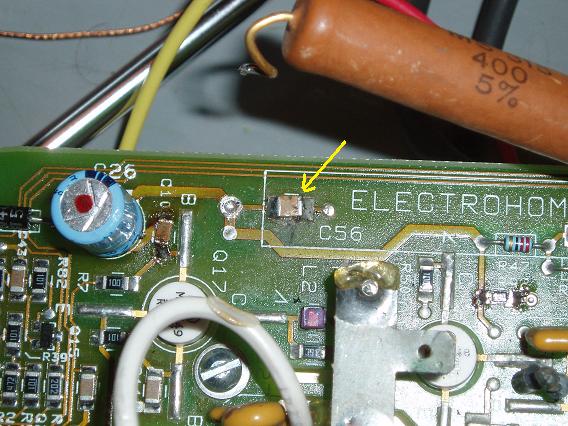
The differences between the board again pointed to the power section and after some (re)soldering....there it was C56...not looking so nice (probably reduced in "motivation" by the heat of the huge resistor and killed in that state by a voltage surge.
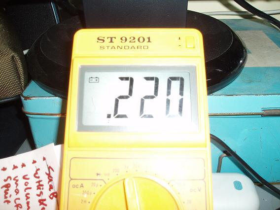
Measurement of this capacitor showed a rather "un-capacitorian"  ohm value of a couple of hundred ohms.....CARBON....This in parallel with a powersupply should trigger it that something might be wrong... ohm value of a couple of hundred ohms.....CARBON....This in parallel with a powersupply should trigger it that something might be wrong...
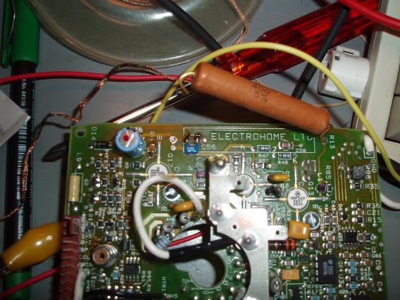
Owww...how I hate SMD's in this place of a powersupply circuit...After cleaning the pcb under C56 replaced the poor thing with a lead-version...
AND there was light
Next thing to do is replace several capactors on these boards for higher temp/voltage versions...
(While we're at it...........If I am going to mount the red C, is it possible to unmount the Red CRT with the pj still hanging?)
| Description: |
|
| Filesize: |
70.79 KB |
| Viewed: |
5248 Time(s) |
|
| Description: |
|
| Filesize: |
44.61 KB |
| Viewed: |
5248 Time(s) |
|
| Description: |
|
| Filesize: |
63.4 KB |
| Viewed: |
5248 Time(s) |
|
| Description: |
|
| Filesize: |
42.35 KB |
| Viewed: |
5250 Time(s) |
|
_________________
"Obviously you're not a golfer"
|
|
| Back to top |
|
|
speedyandre
Joined: 18 Dec 2006
Posts: 291
Location: Netherlands
|
| Posted: Fri Aug 29, 2008 4:32 pm Post subject: |
|
|
Good to see it's alive again 
The tube can be removed quite easy because it's only mounted at the front.
First remove the lens, then the bolts in the bottom are visible.
Remove some bolts at the top bar and the bottom, then you can move the whole tube with it's metal mount out.
Marquee's fall apart when you only look at them 
André
_________________
I'll be broke
|
|
| Back to top |
|
|
Nashou66

Joined: 12 Jan 2007
Posts: 16171
Location: West Seneca NY
|
|
| Back to top |
|
|
Arno P
Joined: 01 Jan 2007
Posts: 282
Location: The Netherlands
|
| Posted: Fri Aug 29, 2008 10:19 pm Post subject: |
|
|
| Nashou66 wrote: | Awesome Arno, Now you need to do the VNB mods I explain on my thread, I'd like to know your results.
Athanasios |
Yep...on my list....I think 1 board needs the CLC449 the other 2 are ok...and I want to exchange the Caps and carbon R's
_________________
"Obviously you're not a golfer"
|
|
| Back to top |
|
|
Arno P
Joined: 01 Jan 2007
Posts: 282
Location: The Netherlands
|
| Posted: Fri Aug 29, 2008 10:20 pm Post subject: |
|
|
| speedyandre wrote: | Good to see it's alive again
The tube can be removed quite easy because it's only mounted at the front.
First remove the lens, then the bolts in the bottom are visible.
Remove some bolts at the top bar and the bottom, then you can move the whole tube with it's metal mount out.
Marquee's fall apart when you only look at them
André |
Ok...so the shift out at the front (could have expected this )
_________________
"Obviously you're not a golfer"
|
|
| Back to top |
|
|
Nashou66
Joined: 12 Jan 2007
Posts: 16171
Location: West Seneca NY
|
| Posted: Fri Aug 29, 2008 11:40 pm Post subject: |
|
|
| Arno P wrote: | | Nashou66 wrote: | Awesome Arno, Now you need to do the VNB mods I explain on my thread, I'd like to know your results.
Athanasios |
Yep...on my list....I think 1 board needs the CLC449 the other 2 are ok...and I want to exchange the Caps and carbon R's |
Read my thread, I use the Intersil EL5166, Its a drop in replacement and a higher bandwidth with lower noise specs, I also went one step further and added the 4.7uf caps they suggest in the data sheet for the buffering. They work great too.
Athanasios
_________________
Don't blame your underwear for your crooked ass~ unknown Greek philosopher
"Republicans believe every day is the Fourth of July, but the Democrats believe every day is April 15." --- President Reagan
One Smart Dog!!!
Marquee High Performance Bellows now shipping!!
Marquee Modifications and Performance Enhancement
Marquee C-element and Bellow removal
|
|
| Back to top |
|
|
Arno P
Joined: 01 Jan 2007
Posts: 282
Location: The Netherlands
|
| Posted: Sat Aug 30, 2008 7:53 am Post subject: |
|
|
| Nashou66 wrote: | | Arno P wrote: | | Nashou66 wrote: | Awesome Arno, Now you need to do the VNB mods I explain on my thread, I'd like to know your results.
Athanasios |
Yep...on my list....I think 1 board needs the CLC449 the other 2 are ok...and I want to exchange the Caps and carbon R's |
Read my thread, I use the Intersil EL5166, Its a drop in replacement and a higher bandwidth with lower noise specs, I also went one step further and added the 4.7uf caps they suggest in the data sheet for the buffering. They work great too.
Athanasios |
I have had some bad experience in my electronics life with higher bandwidth in an exsisting design (updating CD players I/U opamps with high speed....ringing...oscillation better is not always better if the rest remains the same (taming the faster opamp or adapting the circuit to such a speed monster...
_________________
"Obviously you're not a golfer"
|
|
| Back to top |
|
|
Nashou66
Joined: 12 Jan 2007
Posts: 16171
Location: West Seneca NY
|
|
| Back to top |
|
|
Arno P
Joined: 01 Jan 2007
Posts: 282
Location: The Netherlands
|
| Posted: Sat Aug 30, 2008 11:12 am Post subject: |
|
|
| Nashou66 wrote: | No issues here at all, perfect replacement, on Vim and VNB.s ask 1031 and paulB they both used them , and have others.
Athanasios |
I just checked the VNB and VIM and all got the clc449...except 1 neckboard got the 1100 on it...so with 1 clc449 I should be fine
_________________
"Obviously you're not a golfer"
|
|
| Back to top |
|
|
|
|


