| Author |
Message |
Corleone88
Joined: 09 Dec 2006
Posts: 474
Location: France
|
| Posted: Sun Jun 01, 2008 12:09 pm Post subject: |
|
|
| Quote: | Some more suggestions:
1) You should always converge using a pattern from the source and if that is not possible, use "genlocked pattern"
2) Maybe you could post a picture of the screen with convergence off?
3) What kind of convergence adjustments do you have? Ideally all squares should be in the 30-70 range.
|
1. I do that
2. I'll do it next time I start the pj
3. this between 40 and 70. But the problem appears only from the middle point of the picture.
Nobody answers my question about hair-dryer, but if I try to warm up the caps near the power supply for 2-3 minutes and if the problem is there, shouldn't the convergence be stable quickly ?
|
|
| Back to top |
|
 |
Corleone88
Joined: 09 Dec 2006
Posts: 474
Location: France
|
| Posted: Sun Jun 01, 2008 10:09 pm Post subject: |
|
|
I tried to take a picture of the convergences but I get either a very dark picture or a a very bright one  ; ;
Anyway, I tried to measure the distance between the red/blue and the green lines: it is about half a centimer.
|
|
| Back to top |
|
|
Corleone88
Joined: 09 Dec 2006
Posts: 474
Location: France
|
| Posted: Mon Jun 02, 2008 7:22 pm Post subject: |
|
|
|
I noticed that there is a huge cap on the R7622675 board (deflection module I think). On the cap, it is written in german. If I have to change it, do you know the features of this cap ?
|
|
| Back to top |
|
|
Gerbrand
Joined: 13 May 2008
Posts: 199
|
| Posted: Mon Jun 02, 2008 10:03 pm Post subject: |
|
|
Since you are saying that the convergence is drifting in the center: did you use the raster shift for red and green to converge them or did you use the trimpots? At what level is the red/blue raster shift?
Preferably you should use the trimpots.
Gerbrand
P.S. I am also quite curious to see if the caps do it for you. I haven't had the guts to try it yet...
|
|
| Back to top |
|
|
Corleone88
Joined: 09 Dec 2006
Posts: 474
Location: France
|
| Posted: Tue Jun 03, 2008 6:41 pm Post subject: |
|
|
If the trimpots are the ones with the little screws, yes I did that. There is two for vertical blue/red and two for vertical blue/red.
The level of drifting is half a centimeter if I left the pj unplugged for a day. It is around one centimer when I left the pj for more than 2 or 3 days
|
|
| Back to top |
|
|
Corleone88
Joined: 09 Dec 2006
Posts: 474
Location: France
|
| Posted: Fri Jun 06, 2008 9:27 pm Post subject: |
|
|
| Quote: | Sorry - The SMPS. All of the filter caps on the power supply rails. They're the large ones underneath the left hand side:
Not the 3 or 4 caps before the diode (rectifying) bridge in the power supply (R76217055) which are actually the same as the large black on on the right above (which I also never found helped when I replaced it, though if it's completely shot then it might help).
Start with the ones on the left. Careful with your soldering. You don't want to create any shorts or things that may create other problems. Some people around here (ie: me) have been known to hunt for hours to find the problem. Smile
Kal |
I want to be sure which types of caps they are. There are 6 x 1000microF 40V and 4 x 2200microF 16V (the orange ones), but there are 3 others (big black ones) and I don't know their features. Could someone help me on these ones, please (capacity, voltage,...)?
|
|
| Back to top |
|
|
Corleone88
Joined: 09 Dec 2006
Posts: 474
Location: France
|
| Posted: Sat Jun 07, 2008 8:00 pm Post subject: |
|
|
I have got the last 3 : it is 47mF 350V 
After reading Curt's Layout and Setup Tips for 808, I realized that I should get 17V not 17.5V on the SMPS.
Gerbrand, you wrote that it was 17.5v but were you talking about a BG 808 like mine or a 1208 ?
Could it be the reason why I have my convergence problem ?
|
|
| Back to top |
|
|
Gerbrand
Joined: 13 May 2008
Posts: 199
|
| Posted: Sun Jun 08, 2008 1:54 pm Post subject: |
|
|
The service-manual says it should be 17.2 V. As I understand it, above 17V the spot-kill circuit works better. Anything between 17 V and 18 V should be fine.
Gerbtrand
|
|
| Back to top |
|
|
Corleone88
Joined: 09 Dec 2006
Posts: 474
Location: France
|
| Posted: Sun Jun 08, 2008 7:09 pm Post subject: |
|
|
I've ordered new caps. So I keep you informed for the results. 
|
|
| Back to top |
|
|
Corleone88
Joined: 09 Dec 2006
Posts: 474
Location: France
|
| Posted: Thu Jul 03, 2008 2:40 pm Post subject: |
|
|
Hello,
I changed all the big caps on the SMPS board, on the V deflection board and on the H deflection board.
It changes a bit: the first tests seem to show a slight improvement.
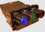
I was wondering what is the big component (a huge metal cap ?) on the Horiz deflection module (R76226775) ??
If this is a cap, what are the specs and has it something to do with convergence stability ?
Thanks for your help.
[img]http://www.hammerheadtech.com/commerce/catalog/showpic.jsp?product_id=10786&czuid=1215096095035[/img]
|
|
| Back to top |
|
|
Ile
Joined: 09 Mar 2006
Posts: 1491
Location: Jyväskylä, Finland
|
| Posted: Thu Jul 03, 2008 7:14 pm Post subject: |
|
|
It's 30uF 330V cap, but it shouldn't have nothing to do with raster stability.
Hsift board caps might help better, that is place where horizontal raster sift is done not hdef board. Check also that yokes are tightened properly. Glueing yokes to tubes belly might help as well, heat can make them to move little...
|
|
| Back to top |
|
|
Gerbrand
Joined: 13 May 2008
Posts: 199
|
| Posted: Thu Jul 03, 2008 9:50 pm Post subject: |
|
|
| Corleone88 wrote: | Hello,
I changed all the big caps on the SMPS board, on the V deflection board and on the H deflection board.
It changes a bit: the first tests seem to show a slight improvement.
|
Too bad it did not work. I think I am not going to try this now.
Gerbrand
|
|
| Back to top |
|
|
Corleone88
Joined: 09 Dec 2006
Posts: 474
Location: France
|
| Posted: Fri Jul 04, 2008 7:17 am Post subject: |
|
|
| Quote: | | Hsift board caps might help better, that is place where horizontal raster sift is done not hdef board. Check also that yokes are tightened properly. Glueing yokes to tubes belly might help as well, heat can make them to move little... |
I noticed an improvement in the horizontal shift (vertical lines are aligned in 30 minutes).
But the horizontal lines are still not aligned after 30 minutes.
What is the board in charge of the vertical shift ? The vertical deflection board ?
|
|
| Back to top |
|
|
Ile
Joined: 09 Mar 2006
Posts: 1491
Location: Jyväskylä, Finland
|
| Posted: Fri Jul 04, 2008 8:51 am Post subject: |
|
|
| Corleone88 wrote: | | What is the board in charge of the vertical shift ? The vertical deflection board ? |
Yes, it's vertical deflection board.
See also if astig is adjusted properly. Adjust midpoint focus between 0-100 on each tube and see if raster is staying in same place. If raster moves, astig is not good enough yet.
|
|
| Back to top |
|
|
Corleone88
Joined: 09 Dec 2006
Posts: 474
Location: France
|
| Posted: Thu Jul 17, 2008 9:54 am Post subject: |
|
|
I carried on swaping some (vertical) boards with spare ones. Lately, it was the vertical deflection board and the shift/horizontal deflection board. It seems that I still have the same problem with the red horizontal lines (vertical shift). The others look OK (stable).
I was wondering if the Barco R7621735 RGB Output Amplifier could be the problem (on the red tube).
They are some caps on it. Some caps can be faulty.
Any chance it can explain the red raster shift ?
Is it possible to swap the output amplifiers for the red tube with the one for the blue tube with no damage ?
|
|
| Back to top |
|
|
Gerbrand
Joined: 13 May 2008
Posts: 199
|
| Posted: Thu Jul 17, 2008 10:46 am Post subject: |
|
|
Hi,
As I wrote earlier I also had (have) problems with a drifting BG808. Recently I redid my tube magnetics and found out that getting this wrong can also cause raster drift problems.
Some things that are important:
1) Make sure the yokes for red, green and blue are perfectly aligned (i.e. the center horizontal lines of the convergence rasters should overlap)
2) Make sure that the focus assembly is aligned with the yoke for each tube. I found out that a misalignment between these can cause focus drift to show up as raster drifts.
3) Make sure your CPC magnets are set up right. Same reason: focus drift and raster drift become correlated, because your spots start moving when focus changes.
So, my conclusion remains: Drift is most likely due to a mechanical set-up issue.
Gerbrand
|
|
| Back to top |
|
|
Corleone88
Joined: 09 Dec 2006
Posts: 474
Location: France
|
| Posted: Thu Jul 17, 2008 12:19 pm Post subject: |
|
|
I would say that you are right if the raster drift would appear also with 15KHz signal.
But this kind of signal shows no stability problem with convergences.
I speak of course about my case
|
|
| Back to top |
|
|
Gerbrand
Joined: 13 May 2008
Posts: 199
|
| Posted: Thu Jul 17, 2008 12:54 pm Post subject: |
|
|
| Corleone88 wrote: | I would say that you are right if the raster drift would appear also with 15KHz signal.
But this kind of signal shows no stability problem with convergences.
I speak of course about my case |
I am not sure (but I am far from an expert)... At higher scan rates all the electronics (including focus) will have to work a lot harder, so thermal issues etc. become much more important. I found out, for instance, that the convergence board fan makes a lot less noise if the mechanical set-up is correct than when it's not. So, with a correct set-up, the projector simply runs cooler.
Gerbrand
|
|
| Back to top |
|
|
Corleone88
Joined: 09 Dec 2006
Posts: 474
Location: France
|
| Posted: Thu Jul 17, 2008 3:26 pm Post subject: |
|
|
| Quote: | Make sure that the focus assembly is aligned with the yoke for each tube. I found out that a misalignment between these can cause focus drift to show up as raster drifts.
|
What do you mean by focus assembly ?
| Quote: | | Make sure your CPC magnets are set up right |
Where are the CPC magnets ? How do you know that they are setup right ?
|
|
| Back to top |
|
|
Gerbrand
Joined: 13 May 2008
Posts: 199
|
| Posted: Thu Jul 17, 2008 4:12 pm Post subject: |
|
|
| Corleone88 wrote: |
What do you mean by focus assembly ?
|
I think the correct name is focus yoke. So the focus yoke and the deflection yoke should be aligned.
See
http://www.curtpalme.com/Barco808_Layout10.shtm
| Corleone88 wrote: |
Where are the CPC magnets ? How do you know that they are setup right ? |
By this I mean the astig magnets (in the same picture). See http://www.curtpalme.com/Astig.shtm on how to set them up correctly.
Gerbrand
|
|
| Back to top |
|
|
|
|


