
|
 |
|
|
| View previous topic :: View next topic |
| Author |
Message |
RogerH
Joined: 14 Jul 2010
Posts: 64
Location: Minneapolis

|
 Link Posted: Thu Sep 09, 2010 5:58 pm Post subject: Good results balancing CRT wear (long) Link Posted: Thu Sep 09, 2010 5:58 pm Post subject: Good results balancing CRT wear (long) |
 |
|
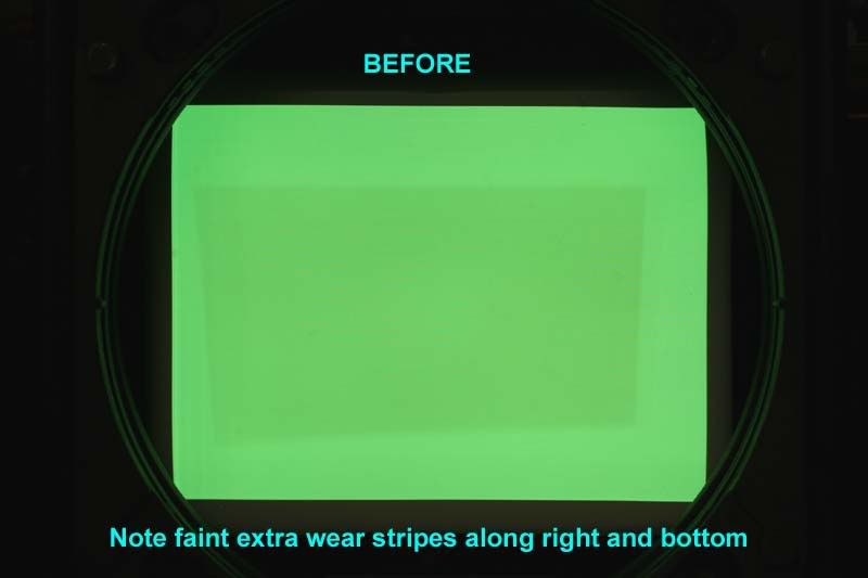
I just finished with what seems to be a successful CRT wear-evening process intended to extend the usable area of a lightly worn XG green tube (one of two Runco XG-852s). I know that this has been done before, but I wasn't able to find much hard information in my searches prior to trying it. I thought I would document the various steps for anyone else that may want to give it a try. This turned out to be a lot easier and much more controllable than expected.
The idea (which has apparently been around a long time) is to wear down and blend virgin phosphor areas surrounding existing undersized or misplaced CRT wear patterns. This is done to allow subsequent use of a larger image area without any visible discontinuities where the original wear area meets the new larger area.
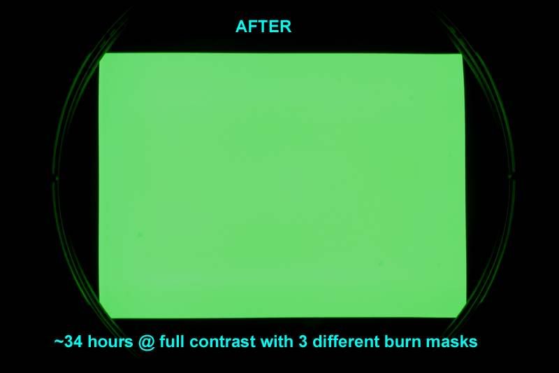
Here are the before and after images of my CRT face after my experiment. Ignore the slight moire in the before picture-it was still sharply focused when the photo was taken. And obviously the "after" image should really be the same brightness of the center of the "before" picture - I didn't do any post processing.
The steps written here are based on the use of my older version of Photoshop 6.0, but if you have a newer version you should be able to translate without any problem.
This procedure was performed on one of a pair of projectors that had apparently been run side-by-side for about 1300 hours. The projector setup had not been optimized, and the wear zones were undersized and poorly centered on both axes. The horizontal offset of each projector from the screen center also required settings that resulted in some vertical keystone distortion in the wear pattern.
The projectors could have been run as-is by operating within the trapezoidal wear zone, but this would have severely under-utilized the phosphor area of all three tubes. And since the R and B tubes are almost mint, this was unacceptable. Although there were many suggestions to just replace the CRT, these projectors were bought as parts machines for my good 852, and CRT replacement wasn't going to happen.
Besides, the end result was far more satisfying and educational.
Creating the Burn Mask Outline
One of the projectors had a straightforward single wear area, but projector B had been repositioned at least a couple times throughout its life, as indicated by multiple overlapping wear patterns. This one would require multiple burn steps to balance the wear, so I decided to do the hardest one first.
Since I would only be working on the green tube, the first step was to create a 640 x 480 rectangle in Photoshop with a solid background of R=0, G=255, and B=0. This was burned to a DVD. There would have been nothing wrong with creating a white burn mask, but I knew I would sometimes forget to mute the R and B tubes, so I decided to make it foolproof.
A DVD player was run through a scaler to increase the number of horizontal lines to the point that electrical defocusing would merge the lines and prevent line burn. I used 1024 x 768, but I did not defocus the projector just yet.
This DVD was then played and a new input memory (appropriately named "burn") was set up to display the filled rectangle as large as possible on the screen. Keystone was set as needed near 0 to display a rectangle on the CRT, not on a projected image. Even with the width and height controls set to 100%, the area was not as large as it could be, so VR5301 on the H-Def board was set slightly out of spec to increase the image width. I set the width to approximately the same width as the internal test patterns, which was about 4-6 mm from the edge of the tube face. Since I would be using the internal all-white test pattern throughout the procedure for reference, the left and right blanking were set to keep the now-larger test pattern from running off the CRT face with any significant energy.
At this point the alignment and raster centering controls were set to make the rectangle as large and as perfectly shaped and centered as possible. It was important to also use a grid pattern to check linearity and lin-balance, because nonlinearity that is not visible on the filled green rectangle would have resulted in uneven wear.
Once the rectangle was centered, shaped, and linear, the settings were saved to memory. A copy of the memory was made, and any subsequent minor adjustments were made to the copy.The green rectangle displayed on the CRT face was then photographed under a low contrast setting using a long shutter time (to avoid scan-banding), low ISO, and in my case, a neutral density filter to help cut the light down. You need to be able to see all of the details of any wear pattern(s) without being washed out by too much light. The camera also needed to be set up as perpendicular and centered as possible on the CRT face to minimize distortion.
The camera image was opened in Photoshop. I grabbed the rectangular selection tool and changed the style to "CONSTRAINED ASPECT RATIO" and entered the numbers of 640 x 480. A selection box was drawn around the illuminated area of the CRT (making sure that nothing was cut off). The image had some distortion which was later corrected. The selection was cropped to eliminate the areas outside the selection. Next, the image was resized from the 640 x 480 (ratio) image to an actual 640 x 480 pixels. EDIT>TRANSFORM>DISTORT was then used to stretch or distort the image as needed to fill the 640 x 480 area with the illuminated image. There was some lens/setup distortion, so the image had some pincushion that was not totally correctable. The photo layer was then locked so that wouldn't get accidently altered.
A new layer was created and the pen tool used to draw the shape of the wear area. This required some guessing, squinting, and readjusting to best align it with the fuzzy wear edges in the photo. The multiple overlapping wear areas that I had required making an outline of each area on a new layer and saving the selections separately (named as step 1, step 2, etc). This required a fair amount of head-scratching at times, because I needed to wear the virgin border phosphor down to match the lightest wear area first, then use a new smaller mask to burn down to the next wear level, and so on.
Creating a Convergence Mask
I found this idea to be useful for tweaking the projector's alighnment/convergence to exactly match the outline(s) that were drawn earlier to match the CRT photo. Unfortunately, this required some trial and error work to find appropriate fill brightnesses in Photoshop, and it was helpful to find a streamlined process for making changes and burning DVDs.
The point of this step was to adjust the color of the background and to fill the saved selection area with just the right brightness of color to make the displayed DVD image as uniform as possible, effectively offsetting tube wear with brighter image areas. This was not used for the actual burning, but just as a visual alignment aid. The 640 x 480 background color was made darker and the worn areas were filled with just the right lighter color to even the CRT image out. These shades did not need to be perfect, and there was some hue imbalance anyway because the worn areas appeared slightly warmer. Here is my 3 level convergence mask:
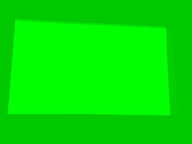
This three level image (in my case) was used to micro-tweak the projector alignment to match the wear areas to their respective mask edges. I found this to be much easier than trying to align a high-contrast black/white (or black/green) edge to the fuzzy and poorly defined CRT wear. This was performed with the lens mounted back on the projector and by viewing a screen rather than by trying to stare into the lens. When I was satisfied with the projector alignment, the settings were saved. From that point on the only tweaks made to alignment controls were on the fly as needed while checking progress during the actual burn.
Creating the Burn Mask(s)
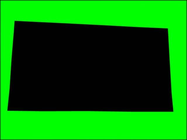
This part was very easy. I simply replaced (with a different color) the exact same outlines in the Photoshop image that were just tweaked into perfect alignment with the Convergence Mask. The outline selection areas were each filled with black (000000) and the background with white (FFFFFF) or pure color. Each individual black-filled outline and green background was then saved as a jpeg. These were burned to DVD to become my actual burn masks. I tried using a small amount of gaussian blur (like up to 0.5 pixel) to soften the mask edges, but I found that the projector defocusing was adequate in my case. This is what one of the three final burn masks looks like:
Performing the CRT burn
The green CRT was electrically defocused to merge scan lines and diffuse the spot energy a bit.
With everything warmed up, I used used the Convergence Mask DVD to recheck alignment. Since the CRT was going to be run pretty hard, the phosphor area was evenly warmed by gradually working up to a full white screen at full brightness (by using contrast control) before hitting it with the bright mask image.
The actual mask DVD was put in the player, and final check of the mask alignment was made. I used masking tape strips on the wall for reference, and I would often make minor width, position, or even RGB point shift changes for a quick correction, although the changes were never saved. I never ran my contrast at 100%, since the drive seemed to flatten out at a lower setting.
Faint but detectable edges of wear began to appear on virgin phosphor within 5-6 hours or so, and the burn time to correct all 3 levels of the wear shown in the photos was a little over 30 hours total. I had to change to my second level burn mask after only about 9 hours. The point is that things can change pretty fast if you are correcting for light wear, so you may want to do this only when you can monitor the progress.
Many times along the way I would go back into Photoshop to make minor mask changes. The left side of my CRT actually balanced out slightly before the right side, probably due to the vertical keystone in the original setup. I replaced the solid green mask background with a slight gradient from left to right (I used 150 to 255 green and 200 to 255 at various times) to avoid over-wearing the left side. I ran the green CRT with the masks until I could no longer detect the original wear area on a projected solid color image, even with the tape lines to guide me to where they were. The first time I displayed a white field, I was ecstatic. There was absolutely no hint of a magenta tint in the center or any lines at all. The wear pattern that was visible on the CRT face under normal ambient light appears at first glance to be gone, but it is only because it has been pushed out to within 4-6mm of the edge of the CRT face.
As a final step, a G2/white balance calibration was performed to calibrate out the new (slightly subdued) tube output. It seemed to come out right where it should be.
Next it's onward to projector A, which I should be able to correct with a single burn mask.
|
|
| Back to top |
|
 |
kschmit2
Joined: 09 Mar 2006
Posts: 1141
Location: Heidelberg, Germany
|
| Link Posted: Thu Sep 09, 2010 6:31 pm Post subject: |
|
|
Great work. Really like it
Kai
|
|
| Back to top |
|
|
garyfritz
Joined: 08 Apr 2006
Posts: 12026
Location: Fort Collins, CO
|
| Link Posted: Thu Sep 09, 2010 7:59 pm Post subject: |
|
|
|
That looks like a minty new tube! Nice job!
|
|
| Back to top |
|
|
Curt Palme
CRT Tech

Joined: 08 Mar 2006
Posts: 24301
Location: Langley, BC
TV/Projector: All of them!
|
| Link Posted: Thu Sep 09, 2010 8:03 pm Post subject: |
|
|
I like this so much I'll ask Kal to transfer the info to the 'advanced procedures on the main site. 
|
|
| Back to top |
|
|
karmat63
Joined: 19 Dec 2007
Posts: 157
Location: Italy
|
| Link Posted: Thu Sep 09, 2010 8:04 pm Post subject: |
|
|
I tried the same process for green and blue CRT on a Marquee 9500 LC, showing uneven wear, being used in a simulator. To have a not so good result, I had to push the PJ (contrast 100, G2 70) for about 200 hours. Then I gave up and decided to accomodate the image inside the wear, obtaining good results, except for film with very light background (i.e.: kind of film like Ice Age). At last I ended in changing the tubes with better ones...
Maybe Necs are faster in wearing tubes?
|
|
| Back to top |
|
|
ecrabb
Forum Moderator
Joined: 13 Mar 2006
Posts: 15909
Location: Utah
TV/Projector: JVC RS40, Epson 5010
|
| Link Posted: Thu Sep 09, 2010 8:26 pm Post subject: |
|
|
I burnt a frickin' game's ammo counter into the corner of my minty green tube in my G70 in about ~120 hours over 4 months or so. It's very subtle when you're looking at the tube, but it's pretty noticeable on an all-white screen. I that running the brightness or contrast at a reasonable level. Sometimes I remembered to turn contrast down, other times I didn't. So, beware.
SC
|
|
| Back to top |
|
|
kal
Forum Administrator
Joined: 06 Mar 2006
Posts: 17860
Location: Ottawa, Canada
TV/Projector: JVC DLA-NZ7
|
|
| Back to top |
|
|
RogerH
Joined: 14 Jul 2010
Posts: 64
Location: Minneapolis
|
| Link Posted: Thu Sep 09, 2010 8:54 pm Post subject: |
|
|
Looking only toward the end goal of trying to balance the CRT wear, I was happy to see the visible wear line show up after the first few hours of running.
On the other hand it was pretty scary to see how quickly you could damage a tube under the right conditions. It seemed that some people who had tried this were not seeing much change after a lot more hours. A lot more. I wonder if it could be even worse under normal sharp focus.
|
|
| Back to top |
|
|
VideoGrabber
Joined: 09 Apr 2006
Posts: 933
Location: Michigan
|
| Link Posted: Thu Sep 09, 2010 10:17 pm Post subject: |
|
|
Roger, this is really great. Thanks for taking the time to document the process, and share the excellent results.
_________________
- Tim
|
|
| Back to top |
|
|
secstate
Joined: 20 Mar 2006
Posts: 720
|
| Link Posted: Fri Sep 10, 2010 1:07 am Post subject: |
|
|
|
I don 't need to do this but thanks for such a great write up.
|
|
| Back to top |
|
|
Spanky Ham
Joined: 22 Mar 2006
Posts: 5643
Location: Comedy Central
|
| Link Posted: Fri Sep 10, 2010 2:52 am Post subject: |
|
|
|
Excellent description. I may try it, as I have a very light wear pattern on my green tube. One thing I might add is that wear pattern on your green looks pretty good. One of the things you trade off by going wider with the raster is sharpness in the corners.
|
|
| Back to top |
|
|
MYoung
Joined: 24 Feb 2007
Posts: 369
Location: Madison, WI
|
| Link Posted: Fri Sep 10, 2010 4:38 pm Post subject: |
|
|
I got pretty decent results using a PC, wireless mouse, and GIMP (freeware graphics program) to wear level my Runco (6PGXtra)...
http://www.curtpalme.com/forum/viewtopic.php?t=18173
I had to burn mine for 180 hours! You can actually still see wear when projecting full white, but it's much better and it got to the point where I was like, eh, good enough. I actually drew the counter wear mask by projecting full screen white with maxed rasters, turning the brightness and contrast all the way down, peering through the lenses at the tube face, and drawing a multi-point polygon in GIMP using a wireless mouse. It is hard on the eyes (did a lot of squinting!), but peering through the lenses magnifies the tube face. Projecting on a screen larger than your normal screen or moving the projector closer to the screen and setting it up would afford the possibility of drawing the mask by looking at the screen, but I didn't want to move my projector. My projector was like your difficult one in that it was moved around a few times in its lifetime. I would draw a mask for the outer most portion needing to be worn-down and working my way in, as opposed to making a pattern to do it all at once, though it looks like you achieved pretty great results going all at once with one pattern. I was just afraid of it wearing into the tube phosphors unevenly, plus the fact that I redrew my counter wear mask multiple times to prevent uneven wear due to convergence drift and drawing one pattern of white seemed easier than worrying about shades of gray.
Nice results!
|
|
| Back to top |
|
|
perisoft
Joined: 29 Aug 2007
Posts: 2920
Location: Ithaca, NY
|
| Link Posted: Fri Sep 10, 2010 6:03 pm Post subject: |
|
|
Nice. I did an auto-levels in photoshop on the post-leveled tube, and the variance was within the tolerance of JPEG compression on the image. I'd be interested to see a PNG or other uncompressed source to see if I could pull out just how closely it matches.
Personally, I'd do this by creating inverse wear maps in photoshop and using those rather than trying to do it by hand - this helps account for subtle shading and distortion in the wear, and also obviously compensates for overlapped wear patterns.
I did something similar, except not reburning, by just using the inverse wear map to overlay the movie output, fixing the problem at runtime, essentially.
_________________
|
|
| Back to top |
|
|
RogerH
Joined: 14 Jul 2010
Posts: 64
Location: Minneapolis
|
| Link Posted: Fri Sep 10, 2010 8:45 pm Post subject: |
|
|
perisoft and MYoung:
perisoft,
I wish I had seen your post before I started. I may not have been using the right keywords in my searches, but I know there is more info out there.
Just to clarify, it did take three different masks to do the balancing on the tube shown, and there was even some minor additional tweaking of those three over the 30+ hours. The multilevel mask that I showed above (the calibration mask) was just a composite of all 3 outlines filled with slightly different shades, intended as an aid for the final alignment of my projector to the drawn outlines. The goal was to display this compensating image that, when correctly aligned in all areas, would appear as a uniform color right through the existing wear. When that happened I knew I was aligned and ready to use the 3 different black-center burn masks in proper sequence.
MYoung:
Using an inverse image overlay in the video path to compensate for wear on the fly (like with ffdshow) can work well, but using an image for a burn mask to permanently balance the CRT phosphor is not as easy as it sounds.
After thinking seriously about doing just that before I started, I came to the conclusion that there would way too many variables that could easily get out of hand.
First, for a given intensity level displayed on the CRT, there is some degree of predictability to the amount of wear that occurs with time. But linear or not, if you have a mask with only full brightness and black on it, you can monitor progress along the way and just stop when you match the new wear to the existing. You may need to alter the mask to protect a newly matched area while you continue to wear deeper in other areas. But you can always monitor progress and stop when you need to make a change.
I see a big problem with using a graded-level mask. It would require learning exactly what those graded levels need to be to in order to bring all of the various brightnesses of virgin or semi-virgin (can you have semi-virgin?) phosphor down at the same rate. In effect, the gamma of a graded-level mask would have to be just right to even out all the different shades at one time.
I suspect that wear is very non-linear with respect to beam intensity, due to phosphor heating and limited heat dissipation through the glass aggravating the wear. For example, if I can incur a certain level of wear in 10 hours at full intensity (as I did), would half intensity incur the same wear over 20 hours? Very unlikely, otherwise we would be killing our tubes in no time under normal operation. It would seem more likely that the wear or burn increases exponentially faster with higher intensities. It's the value of that exponent that is the mystery.
A burn mask created from an actual image would have to start off as a photo like my "before" image. The image gain (contrast) and bias (brightness) would have to be altered to set the two points that we definitely do know: the center of the mask should be black (so we don't wear the existing pattern any further), and the border of the mask should be at the maximum of 255 (or 100%). The problem is that the shades in between cannot be expected to wear evenly with the border, unless the third variable (gamma) is altered just the right amount.
Just to use a guessing example, say we have a simple 3 level CRT wear pattern with brightness levels of 60%, 80%, and 100% (in the virgin area) that we want to wear down to a uniform 60% in all areas. This would require a burning mask of 0% (black) , some unknown %, and 100% respectively to bring all of the phosphor to an even wear level at the same time. I suspect that the burn mask levels would actually have to be compressed at one end of the scale, but I wouldn't know which end or how much.
This could be learned through controlled high-IRE grayscale burn experiments on bad tubes (I did a short test on the border of a toast tube just to get a feel for what to expect). You could learn how duration affects the burn for fixed levels, and secondly how the IRE level influences the burn for a given duration.
Tackling that second part would require more tubes and patience than I have. Sticking to only 2-level masks (black and white or 100% color) and making burn duration the only variable seemed much more attractive in the end. Even if I had to deal with ammo counter or logo burns, I would opt to make a bunch of different black/white masks of any shape needed and make adjustments over time.
And this is where the time/cost tradeoff pushes most people toward the simpler solution-replace the CRT.
|
|
| Back to top |
|
|
that1crzywhtguy
Joined: 26 Mar 2017
Posts: 84
Location: Martinez, CA
|
| Link Posted: Sat Feb 10, 2018 6:46 pm Post subject: |
|
|
I know this is an ancient post by now, but I wanted to reach out and say thanks!!! I had to sort of tweak the procedures to work in my setup but this really got me started, and well, the results were excellent!!!
Thanks again!
Phosphor wear before and after. https://imgur.com/gallery/EuIYW
|
|
| Back to top |
|
|
kal
Forum Administrator
Joined: 06 Mar 2006
Posts: 17860
Location: Ottawa, Canada
TV/Projector: JVC DLA-NZ7
|
|
| Back to top |
|
|
that1crzywhtguy
Joined: 26 Mar 2017
Posts: 84
Location: Martinez, CA
|
| Link Posted: Sat Feb 10, 2018 7:08 pm Post subject: |
|
|
Totally! My tubes weren't very worn, and it took way more hours of runtime, but worth it in the end. You can see the original owner didn't have it calibrated WAY to small, but it wasn't maximizing tube face either. Also, I really want to enjoy some 4:3 gaming with retro systems, so getting rid of the 16:9/2.35:1 wear pattern was really desirable to me.
Now to do blue and red, but those were less worn, so hopefully this will be much quicker. 😁
|
|
| Back to top |
|
|
|
|
|
|
|
|
You cannot post new topics in this forum
You cannot reply to topics in this forum
You cannot edit your posts in this forum
You cannot delete your posts in this forum
You cannot vote in polls in this forum
You cannot attach files in this forum
You can download files in this forum
|
Forum powered by phpBB © phpBB Group
|
|


