| View previous topic :: View next topic |
| Author |
Message |
Nashou66
Joined: 12 Jan 2007
Posts: 16171
Location: West Seneca NY

|
|
| Back to top |
|
 |
CRT_Ben
Joined: 28 Aug 2006
Posts: 1684
Location: Northern Virginia
|
 Link Posted: Wed Aug 05, 2009 8:16 pm Post subject: Link Posted: Wed Aug 05, 2009 8:16 pm Post subject: |
 |
|

My apologies! I saw the picture of the fan modification and incorrectly assumed that the p14 mod "section" was over. Sorry about that Parts are being ordered...
And thanks again for your writeups in this thread...they're invaluable!
|
|
| Back to top |
|
|
Nashou66
Joined: 12 Jan 2007
Posts: 16171
Location: West Seneca NY
|
| Link Posted: Wed Aug 05, 2009 10:01 pm Post subject: |
|
|
| CRT_Ben wrote: |
My apologies! I saw the picture of the fan modification and incorrectly assumed that the p14 mod "section" was over. Sorry about that Parts are being ordered...
And thanks again for your writeups in this thread...they're invaluable! |
Your welcome Ben!!! The past three post of mine were all done from my iPhone while helping a friend out in Lewiston, NY on a future Major remodel Job. Nice View from this place you can see Toronto and Hamilton as clear as day!!!
Athanasios
_________________
Don't blame your underwear for your crooked ass~ unknown Greek philosopher
"Republicans believe every day is the Fourth of July, but the Democrats believe every day is April 15." --- President Reagan
One Smart Dog!!!
Marquee High Performance Bellows now shipping!!
Marquee Modifications and Performance Enhancement
Marquee C-element and Bellow removal
|
|
| Back to top |
|
|
1031
Joined: 22 Mar 2006
Posts: 657
Location: Finland
|
|
| Back to top |
|
|
HK-Steve

Joined: 15 Jul 2006
Posts: 849
Location: Switzerland
TV/Projector: Marquee 9500, Epson 8100
|
| Link Posted: Thu Aug 06, 2009 7:38 am Post subject: |
|
|
I replaced the rear heatsink completely, then added 4x fans for cooling.
I have a thread with all the details,
http://www.avforums.com/forums/crt-projectors/511561-marquee-rear-heatsink-modification.html
The AVS link does not work, I couldn't even find the original thread, Oh Well.
Yes, the bottom cover can be attached,
I used screws through the side to hold it, I did originally do it from underneath, which you can see in the pics, the black dots in the corners are screws.
I will take a pic to show you later today of the new way.
Cheers
Steve
|
|
| Back to top |
|
|
Nashou66
Joined: 12 Jan 2007
Posts: 16171
Location: West Seneca NY
|
| Link Posted: Thu Aug 06, 2009 11:12 am Post subject: |
|
|
| HK-Steve wrote: | I replaced the rear heatsink completely, then added 4x fans for cooling.
I have a thread with all the details,
http://www.avforums.com/forums/crt-projectors/511561-marquee-rear-heatsink-modification.html
The AVS link does not work, I couldn't even find the original thread, Oh Well.
Yes, the bottom cover can be attached,
I used screws through the side to hold it, I did originally do it from underneath, which you can see in the pics, the black dots in the corners are screws.
I will take a pic to show you later today of the new way.
Cheers
Steve |
You Mean this thread 
http://archive2.avsforum.com/avs-vb/showthread.php?t=754506&highlight=Marquee+Fans
Athanasios
_________________
Don't blame your underwear for your crooked ass~ unknown Greek philosopher
"Republicans believe every day is the Fourth of July, but the Democrats believe every day is April 15." --- President Reagan
One Smart Dog!!!
Marquee High Performance Bellows now shipping!!
Marquee Modifications and Performance Enhancement
Marquee C-element and Bellow removal
|
|
| Back to top |
|
|
HK-Steve
Joined: 15 Jul 2006
Posts: 849
Location: Switzerland
TV/Projector: Marquee 9500, Epson 8100
|
| Link Posted: Fri Aug 07, 2009 1:34 pm Post subject: |
|
|
Thanks, I knew some one with better search skills would find the post.
Cheers Athanasios
Cheers
Steve
|
|
| Back to top |
|
|
ralpharch
Joined: 02 Nov 2007
Posts: 211
Location: Derwood
|
| Link Posted: Fri Aug 07, 2009 8:20 pm Post subject: |
|
|
Thanks to both of you for the directions and photos. Still trying to fix my intermittent sync problem but in the meantime I cancelled my order for the cheap Optoma HD 20 1080p. Figure I will play around with the Marquee a little more until its either fixed or the news comes out on all the new digitals at CEDIA in a month or so
I have now cleaned the ICs - hadn't done all the ones on the HDM daughter card before Steve's post in another thread. Will have to wait and see if this got it. An intermittent sync is such a problem as it can go for hours without a problem and then show up like yesterday went for 5 hours before appearing. So that heat sync mod may really be what it takes to "fix" my sync problem. I'll have to wait and see if it comes back at all now that I have cleaned some extra ICs and connectors - this time with a toothbrush and deoxit.
One thing I did notice when cleaning the ICs and connectors was a waxy glob on the HDM daughter board. (see attached bad photo). Is something like this normal - for example something that was added for taking the heat away?
|
|
| Back to top |
|
|
Nashou66
Joined: 12 Jan 2007
Posts: 16171
Location: West Seneca NY
|
| Link Posted: Fri Aug 07, 2009 9:06 pm Post subject: |
|
|
Ralph thats Hot glue, There is a transistor there that sometimes moves and can break. So some boards have the hot glue to keep it in place. Some time they also use hot glue to stop resonances but not sure if this board is one that suffers from that. I'll look at my schematics for that piece IIRC it should be a transistor, maybe that part is part of the sync circuit? I'll post back when I look it up.
Athanasios
_________________
Don't blame your underwear for your crooked ass~ unknown Greek philosopher
"Republicans believe every day is the Fourth of July, but the Democrats believe every day is April 15." --- President Reagan
One Smart Dog!!!
Marquee High Performance Bellows now shipping!!
Marquee Modifications and Performance Enhancement
Marquee C-element and Bellow removal
|
|
| Back to top |
|
|
HK-Steve
Joined: 15 Jul 2006
Posts: 849
Location: Switzerland
TV/Projector: Marquee 9500, Epson 8100
|
| Link Posted: Sat Aug 08, 2009 8:08 am Post subject: |
|
|
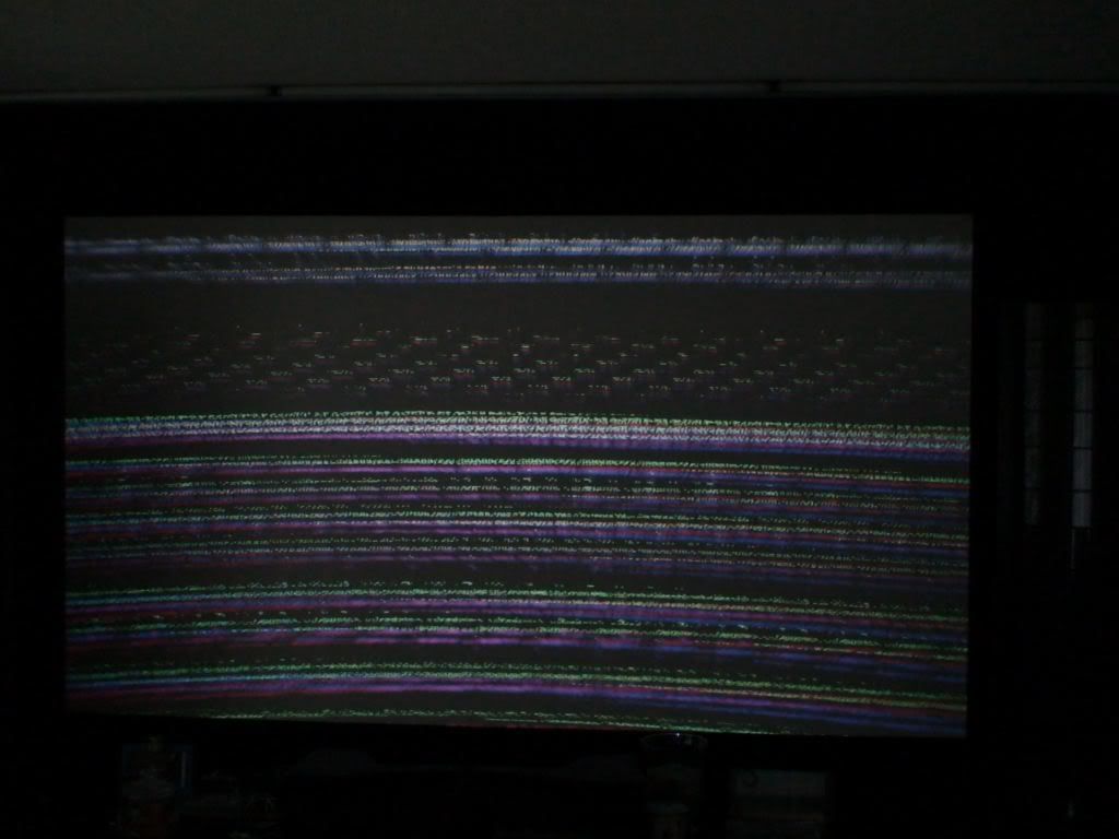
You should replace Q501, this is a 2N7000,
This transistor is one of the replacements when you have HDM problems.
It has nothing to do with sync, but it seems to fix many issues on the HDM-D.
The glue is to hold a resistor as it is soldered to the transistor then the board.
It has nothing to do with sync, it does vertical centering.
What VIM are you using?? 2005 or 2035??
is this the same sync problem that I had with a pic like this??
Cheers
Steve
|
|
| Back to top |
|
|
Nashou66
Joined: 12 Jan 2007
Posts: 16171
Location: West Seneca NY
|
|
| Back to top |
|
|
HK-Steve
Joined: 15 Jul 2006
Posts: 849
Location: Switzerland
TV/Projector: Marquee 9500, Epson 8100
|
|
| Back to top |
|
|
draganm
Joined: 08 Mar 2006
Posts: 8990
Location: Colorado
|
| Link Posted: Sun Aug 09, 2009 9:51 pm Post subject: |
|
|
guys I've been having great success with this basic re-build (mild upgrade work  . I've said it before but thanks to everyone who has contributed to both this thread and the ones that preceeded it. People have been REALLy happy with the results so far and if you were wondering, the reliability of the Marquee is great after doing just the basic capacitor and resistor upgrades. ( I haven't done any of the op amps or inductors for various reasons.) . I've said it before but thanks to everyone who has contributed to both this thread and the ones that preceeded it. People have been REALLy happy with the results so far and if you were wondering, the reliability of the Marquee is great after doing just the basic capacitor and resistor upgrades. ( I haven't done any of the op amps or inductors for various reasons.)
One thing that was never covered in this thread is the newer marquee VIM's. I know Athan did some work on his older 2005-03 VIM and had problems, so I thought maybe it's time to take the newer VIM package and do a more conservative approach, not get so crazy with adding inductors and such. My main reasion for asking is that Scot has expressed some reservations with inductors and when they're specced incorrectly, they start to acts as capacitors. I'm wondering if this was the cause of the some of the early glitches?
Anyway, my idea is to do stuff that's proven, something like the Basic VDC (AKA TSE) 1080P peaking circuit combined with the dot, snap, and line fix.
Maybe add some filtering or de-coupling at the power input section, but it would have to be neat looking, compact, and not have parts sticking up like dead bugs  I could enlist some help on this as it's well beyond me but I have some friends who are brilliant with Electronics Engineering. Most importantly the schematics are available so no one would be diving into this blindly. I think the biggest challenge is identifying what frequency noise is on the VIM power rails and then targeting it specifically with the correctly specced caps or inductors or a combination of both? Anything I find out I will gladly post here for everyone to share and I can even take killer pics up close. I could enlist some help on this as it's well beyond me but I have some friends who are brilliant with Electronics Engineering. Most importantly the schematics are available so no one would be diving into this blindly. I think the biggest challenge is identifying what frequency noise is on the VIM power rails and then targeting it specifically with the correctly specced caps or inductors or a combination of both? Anything I find out I will gladly post here for everyone to share and I can even take killer pics up close.
As before, If it's successful, I will be offering this through the forum for people who cannot do it for themselves or simply don't want to take chances with their boards. Thereby continuing improvements to the older pre VDC marquee's and also providing some $ support to the forum as well. In case your wondering, yes i already asked Curt and he's totally cool with this 
So who's up for this, has anyone tried the VDC (AKA TSE) 1080P peaking circuit yet? I've actually seen this on a VIM but hot have actually tried to do it from scratch on an older board.
Oh and one other thing, the newer VDC VIM had all the audio crap removed. I wonder if scrapping all this junk off the older VIM's would help in any way?
On your mark, get set, Let the bashing begin 
|
|
| Back to top |
|
|
Nashou66
Joined: 12 Jan 2007
Posts: 16171
Location: West Seneca NY
|
| Link Posted: Sun Aug 09, 2009 11:41 pm Post subject: |
|
|
Hi Dragan. I have taken all the audio stuff off my vims and they work fine afterwards. One reason to do so is to lessen the load on the 5 volt rails and get rid of any noise these circuits may feed back tot he power rails. On the use of Inductors for the 5 and 15 volt rails, I see no reason not too, if you have an inductor kit it be easy to scope the rails to find the right inductor. One thing though is the 5 volt rail is finicky if the voltage drop too low, so the inductors used on those rails must have a very low DCR. Adding them to the fuses there is easy and you can make it look neat if you take time to bend them into position correctly as on the CLM mod in this thread. I used 220-270 uh inductors. One thing is inductors are a bit more expensive than caps, so finding the right ones can get costly. I just went with those values as its the values MP used on the 5 volt CLM rails. Nothing Scientific about my choice but I figured if its the same voltage rail the same noise might be on that as well, but this was earlier in my research and now realize it be best to scope that rail with different inductors. the tants that are there can be upped in value to 22 or 33 uf, I have tried Oscons there but those do not have the longevity in hours as tants or electrolytic's at high operating temps . but if used at normal levels and not 24/7 like in a simulator, Oscons could do a great Job there .
Adding more capacitance filtering to the op amps , not just the RGB one can also help and some beefier caps in other spots to help with extra power requirements, theory there is if lots of the circuitry uses the same power rails if one is required to draw a bit extra it can take away from the rgb op amps. Those Amps operate best when the voltage doesn't fluctuate to much so a nice steady and smooth power rail helps immensely i would assume. I still plan on adding the VIm to the thread but want to get the Blend up and running permanently and then i need to set up a screen and PJ for the testing. I plan to use an 8500 chasis with the Thomas 9 inch tubes and modified VNB's for them. This machine will then be the test bed for the Vim upgrades and also the Barkenstien Yolks I have been messing around with. But the blend is # 1 for now. aiting for my TV-One unit to get back to me from repairs.
Athanasios
_________________
Don't blame your underwear for your crooked ass~ unknown Greek philosopher
"Republicans believe every day is the Fourth of July, but the Democrats believe every day is April 15." --- President Reagan
One Smart Dog!!!
Marquee High Performance Bellows now shipping!!
Marquee Modifications and Performance Enhancement
Marquee C-element and Bellow removal
|
|
| Back to top |
|
|
1031
Joined: 22 Mar 2006
Posts: 657
Location: Finland
|
|
| Back to top |
|
|
tse
Joined: 03 May 2006
Posts: 1014
Location: Sweatbucket, Fl.
|
| Link Posted: Mon Aug 10, 2009 3:29 pm Post subject: |
|
|
Make sure that the variable caps are low value (Maximum value < 20pF) or streaking and/or oscillations can happen. Use the proper test pattern (SMPTE133). Don't over do it. The mod gives bandwidth good enough for 2048 x 1536 @ 60Hz which requires much more bandwidth than 1080p @ 60Hz.
Scott
_________________
"Were we directed from Washington when to sow and when to reap, we would soon want bread."
Thomas Jefferson
|
|
| Back to top |
|
|
Nashou66
Joined: 12 Jan 2007
Posts: 16171
Location: West Seneca NY
|
|
| Back to top |
|
|
draganm
Joined: 08 Mar 2006
Posts: 8990
Location: Colorado
|
| Link Posted: Mon Aug 10, 2009 4:56 pm Post subject: |
|
|
| Nashou66 wrote: | | Hi Dragan. I have taken all the audio stuff off my vims and they work fine afterwards. One reason to do so is to lessen the load on the 5 volt rails and get rid of any noise these circuits may feed back tot he power rails. Athanasios |
thanks, those are all good little tid-bits to consider. i'll print all this stuff out when I sit down with my EE team
| tse wrote: | Make sure that the variable caps are low value (Maximum value < 20pF) or streaking and/or oscillations can happen.
Scott |
so it sounds like this can be really finicky and if not done right will cause problems like Jarmo had.
| tse wrote: | Use the proper test pattern (SMPTE133). Don't over do it. The mod gives bandwidth good enough for 2048 x 1536 @ 60Hz which requires much more bandwidth than 1080p @ 60Hz.
| Quote: | The variable caps on the VIM help to compensate for the low pass filter made up of U13 series resistance (red channel) and all the capacitances between U11 and U14 input. Use the variable caps to make one pixel on/one pixel off test pattern as near the same as possible to the one line on/one line off test pattern.
Signals shown are one pixel on/one pixel off series at 2048x1536@60Hz. Top trace is output of U11. Middle trace is input to U14 with no peaking. Bottom trace shows input to U14 with peaking circuit added.
The neck card is essentially another low pass filter that can be somewhat compensated for by (over)peaking the output of U11.
This mod gives enough bandwidth for pixel clock 240MHz needed for QXGA (2048x1536@60Hz). Standard configuration is a little low for 150MHz pixel clock or 1600x1200@60Hz or 1920x1080@60Hz. |
Scott
|
thanks for replying Scott. So basically adding the eletronic components is the easy part. From what I have understood so far, this requires a scope and VIM extender card to actually dial-in the proper wave-form with the vari-caps , corect?
|
|
| Back to top |
|
|
tse
Joined: 03 May 2006
Posts: 1014
Location: Sweatbucket, Fl.
|
| Link Posted: Mon Aug 10, 2009 5:18 pm Post subject: |
|
|
The extender card helps alot but you can do it with the VIM in place and a short tweeker. The projected image is the best display for making the adjustment.
Scott
_________________
"Were we directed from Washington when to sow and when to reap, we would soon want bread."
Thomas Jefferson
|
|
| Back to top |
|
|
Nashou66
Joined: 12 Jan 2007
Posts: 16171
Location: West Seneca NY
|
| Link Posted: Mon Aug 10, 2009 5:30 pm Post subject: |
|
|
Its easy to make the extender card Dragan, I think I list the boards and connectors I used in this thread somewhere.
For doing the adjustment on the peaking circuit its best to have an extender card, but you can adjust put it back in adjust put it back in etc. Just it take more time that way. And I found out tweeking one peaking circuit on a VIM and then putting it in a different marquee you need to re tweek it again somewhat, it depends on how closely they are color calibrated. Found all this out while working on the blend. before i got the two PJ's more closely calibrated and i was swapping the VIMs around to find that problem I had is when i noticed it. if i swapped the Vims i had to adjust the peaking circuit again. But now that they are more close in calibration , if i swap Vims they are pretty close. Did you notice this also Scott or am could there be another cause?
But its really cool adjusting the variable caps while viewing the one on one off SMPTE pattern. you have it nailed if the lines are black and defined well, and even in color(verticle and horizontal blocks) your off if they are redish or blueish, they change colors depending on if you over or under peak.
I should take pics of how the pattern changes , if i get time.
Athanasios
Athanasios
_________________
Don't blame your underwear for your crooked ass~ unknown Greek philosopher
"Republicans believe every day is the Fourth of July, but the Democrats believe every day is April 15." --- President Reagan
One Smart Dog!!!
Marquee High Performance Bellows now shipping!!
Marquee Modifications and Performance Enhancement
Marquee C-element and Bellow removal
Last edited by Nashou66 on Mon Aug 10, 2009 7:41 pm; edited 1 time in total
|
|
| Back to top |
|
|
|
|


