| View previous topic :: View next topic |
| Author |
Message |
Nashou66
Joined: 12 Jan 2007
Posts: 16171
Location: West Seneca NY

|
 Link Posted: Sat Mar 08, 2008 11:36 pm Post subject: Marquee Modifications and Performance Enhancement Link Posted: Sat Mar 08, 2008 11:36 pm Post subject: Marquee Modifications and Performance Enhancement |
 |
|
Another marquee thread! Why you ask? This is to augment the already great thread
of marquee maintanence started by Mike parker way back in 2003. There was an earlier
thread but I could not find it, i think its now linked to his newest thread. I was not into
CRT's at that time although I always dreamed about having a CRT set up in my theater.
This is the original link to part 2 of Mikes thread from AVS Archives:
Marquee Maintenance and Upgrade Part 2
The Revived thread is located here on Curt's site in the advanced procedures section.
Most of what I have done was from searching the archives looking for anything Marquee
related or something that might benefit my quest to mod my Marquee on my own. The upgrades
I have done so far i did at a risk, I have no background with electronics and have learned from
mistakes and from the help of others on this and AVS forums, many thanks to them, and some
of the things i have done were suggested somewhere else having not been assured that they
would work or harm the Projector... but even so i grabbed my barely used soldering iron and
began my quest. One of the first mods i did was to the HVPS. This is mentioned in the
MMT(Marquee Maintenance Thread), there is where I heard of Jeahong Lee who discovered
the noise lowering by changing the Carbon Comp resistors with ceramics. I did a search in
the archives for any post by him and from in one of his threads is where McPherve made
many suggestions about improving the marquee by replacing older parts with better newer quality
parts and possible "Mods". Mike P., KBK, bblue, and others discuss and suggest different ideas
about the marquee which also was very valuable and quite interesting and fun to read.
I will come back later to this first post and try to add any links I used while doing the upgrades
to my Marquee. I never thought i would be doing anything like this and never kept notes , so its
scattered all over both forums and between three computers I have
Time is a rare resource so I may not get to or add new info often.
Lets all have fun doing this and Since I am not an EE any comments or suggestions are
absolutely welcome and appreciated. And those techies out there please correct me and
call me out on any issue you may have , that way others will take note and decide on
their own if they should continue with anything that is being discussed.
List of direct links to all the mods
HVPS mod Link
Focus Board Mod
Video Neck Boards Mods
LVPS Cap Upgrades
Vertical Deflection Module
Convergence Module Mod
Jarmos Rear heat sink Temp controlled fan Boards and Schematics
May 2009 update:
For those who can not do these mods themselves Draganm is offering these mods at a vary fair price. So if you have 10 thumbs Dragnm is the guy for you. I appreciate those who have asked me to do the work but I have no time for these as my other projects take precedence.
Here is the link for the Mods:
Marquee HD Mods by Draganm
Athanasios
_________________
Don't blame your underwear for your crooked ass~ unknown Greek philosopher
"Republicans believe every day is the Fourth of July, but the Democrats believe every day is April 15." --- President Reagan
One Smart Dog!!!
Marquee High Performance Bellows now shipping!!
Marquee Modifications and Performance Enhancement
Marquee C-element and Bellow removal
Last edited by Nashou66 on Wed Apr 07, 2010 3:49 am; edited 11 times in total
|
|
| Back to top |
|
 |
Nashou66
Joined: 12 Jan 2007
Posts: 16171
Location: West Seneca NY
|
| Link Posted: Sat Mar 08, 2008 11:59 pm Post subject: Low Voltage Power supply Heater filament fix |
|
|
The first installment I thought should be the Heater filament fix . this is to save the tubes
from over voltage to the heater elements in the tube causing premature failure.
remove the LVPS from the projector and open up the case being careful to remove all
connectors before completely opening. Locate the 6.35 voltage trim pot on the section
that houses the fans. a 470 ohm metal film resistor and a 20ohm trim pot is needed.
here is a close up pic.

remove the old pot that causes the drifting of the voltage as shown here

then I wrapped one end of the resistor around the existing resistor as shown, I did
this backward for the pics, I should have cut the trace first as in the next pic after this
one.

this pic you can see the trace cut and the resistor soldered to the other
resistor, i found it easier to keep the lead on the resistor then cutting it after its all done.

Then I fed the other lead through the whole that the cut trace goes to. Make sure all the
old solder is removed so the pin from the trim pot can also fit.

Now with the new trim pot in place.

Back side of board showing lead from resistor and trim pot leads.

Solder the pins from under and put power supply back together and test the output before
you connect P14. trim pot to get as close to 6.35 as you can.
While you have the cage for the power supply out you can cut the screen area to allow better
airflow and it could also help reduce and turbulent noise, i used a pair of metal snips then a file
to smooth it out. I also added dynamat to the inside stop any vibrations in the chasis.
A fan noise post will also be in this thread too.

Parts needed: I get mine from Newark:
http://www.newark.com/jsp/search/productdetail.jsp?SKU=62J1506
http://www.newark.com/jsp/search/productdetail.jsp?SKU=94C3568
Athanasios
_________________
Don't blame your underwear for your crooked ass~ unknown Greek philosopher
"Republicans believe every day is the Fourth of July, but the Democrats believe every day is April 15." --- President Reagan
One Smart Dog!!!
Marquee High Performance Bellows now shipping!!
Marquee Modifications and Performance Enhancement
Marquee C-element and Bellow removal
Last edited by Nashou66 on Fri Oct 05, 2012 3:35 am; edited 13 times in total
|
|
| Back to top |
|
|
Nashou66
Joined: 12 Jan 2007
Posts: 16171
Location: West Seneca NY
|
|
| Back to top |
|
|
Nashou66
Joined: 12 Jan 2007
Posts: 16171
Location: West Seneca NY
|
| Link Posted: Sun Mar 09, 2008 12:53 am Post subject: High Voltage Power Supply |
|
|
I first saw this mod on the MMT and then went to Jeahong Lee's thread:
 some way to improve PQ greatly in Marquee 9500 some way to improve PQ greatly in Marquee 9500
The reason for this mod is to remove the older noisy carbom composition resitors,
these are in the G2 signal and the resulst vary from projector to projector but there
is a reduction in background noiseespecially in lighter scenes. I also noted an increase
in shadow details.
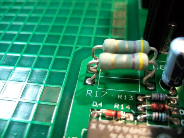
Remove HVPS and open up unpotted section.
remove all the carbon comp resistors and replace with 2 watt ceramic ohmites of same value.
Also I changed the 4 large caps with polypropylene caps of same value. this doesn't have to
be done unless the caps are leaking or not close to rated value. Mine were fine but I did it anyhow.
What i am going to say next is only after you do this mod and have a problem with the other
tubes staying on when having only one tube on.
to test for the tube intensity anomaly as I call it:
After you put power supply back in turn on projector and bring up the grid. Now select one
color at a time by pressing color then 1(red) 2 (green) 3 (blue). Do one at a time starting
with red... look into the other tubes and see if you can see the grid displaying on another color .
A very very light grid is not too bad of a problem and wont show up on the screen.
However Some of use who have done this complete mod with caps and resistors have had it
where when one color is on the tother tube or tubes are also lit up to the point it can show
up on the screen. I and one other person have decide to measure the value of the resistor we
took out and replaced with the 560kohm ones. Mine were close to 680kohm, I thought that if i
increased the value of the ceramic resistor to that of the old drifted ones the anamoly might
go away, which it did. now I did not notice any ill effect so far with this increase. And if you don't
notice a problem with the projected image then leave the 560kohms in. It might only happen
with the cap changes not sure but post back your results here, I would like to find out if others
have noticed this as well. Mike Parker has not noticed this happening to the ones he has done
and suggested to me not to change the value, howwver it was way to bright and it was affecting
my picture. After the fix all is well after many hours of use.
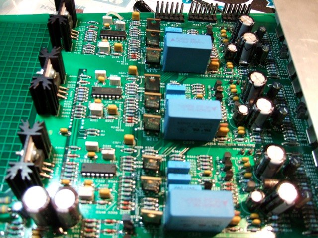
Here are pics of the HVPS:
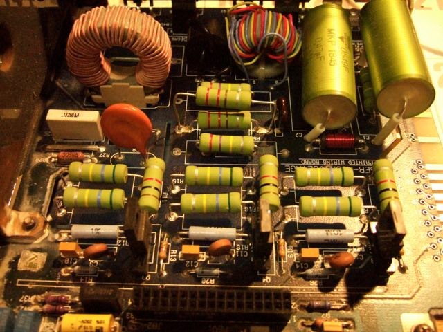

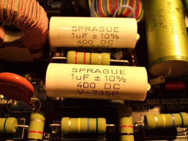
Leave room for resistors to breath !!


Part numbers for Ohmite Resistors
560K 2W OY564K 6
1K OY102K 3
220 2W OY221K 2
270K OX274K 2
470K OY474K 1
Caps:
http://www.newark.com/jsp/search/productdetail.jsp?SKU=18M2493
http://www.newark.com/jsp/search/productdetail.jsp?SKU=37M0653
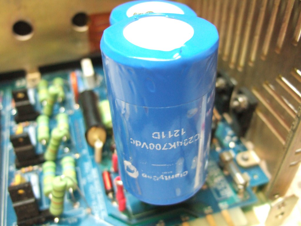
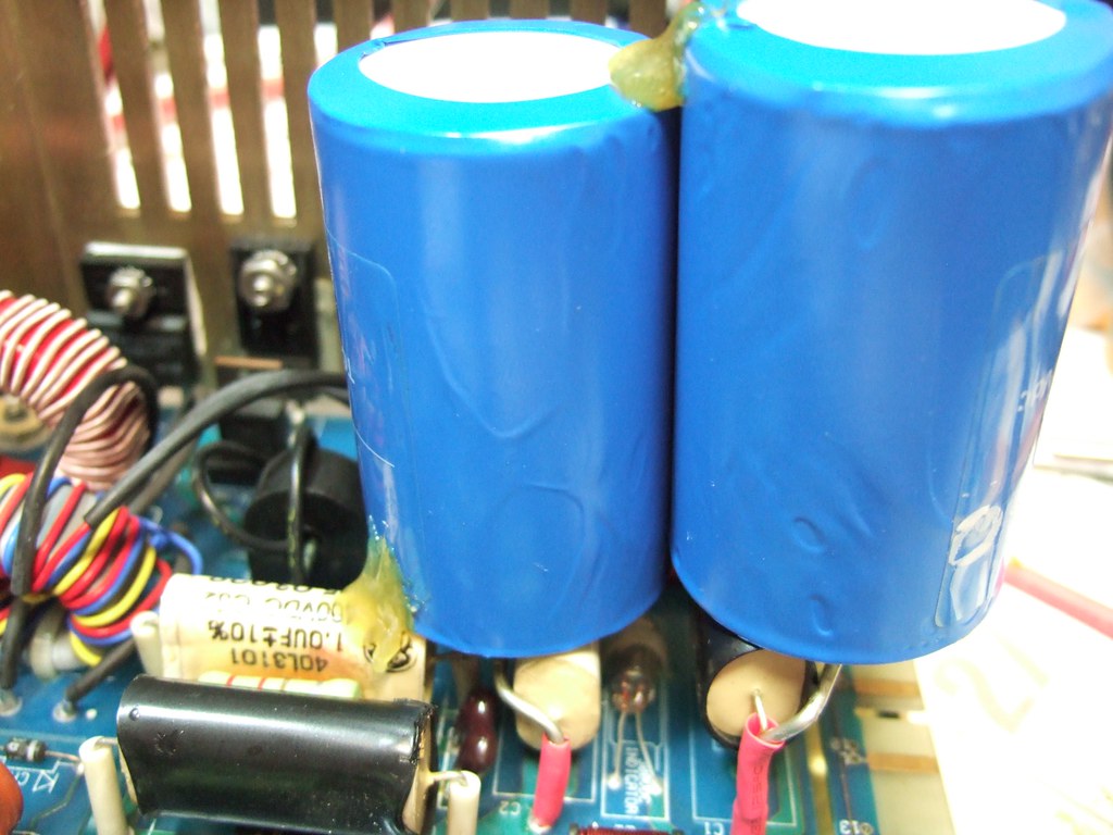
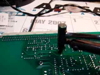
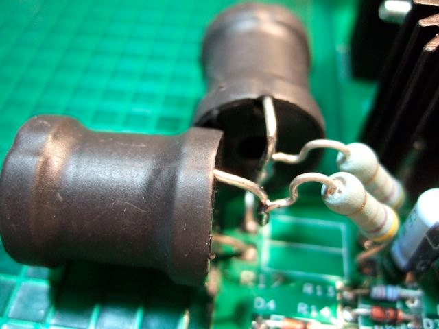
EDIT: To keep the HVPS regulated better for the transients from Dark to Bright
with out blooming Chris Stevens added 4 125f 100 volt Wet tantalums to the 390 volt rail
coming into the HVPS. Well to find those caps cheap is not easy. So I came up with using A single HV Film Cap.
here it is on Justins HVPS.

Athanasios
_________________
Don't blame your underwear for your crooked ass~ unknown Greek philosopher
"Republicans believe every day is the Fourth of July, but the Democrats believe every day is April 15." --- President Reagan
One Smart Dog!!!
Marquee High Performance Bellows now shipping!!
Marquee Modifications and Performance Enhancement
Marquee C-element and Bellow removal
Last edited by Nashou66 on Wed Jan 21, 2015 11:24 pm; edited 10 times in total
|
|
| Back to top |
|
|
Nashou66
Joined: 12 Jan 2007
Posts: 16171
Location: West Seneca NY
|
| Link Posted: Wed Mar 12, 2008 11:09 pm Post subject: Focus Board upgrades. |
|
|
Now moving on to the Focus board. I have two boards here that I upgraded.
The first was one of the the newer boards 50-2034-02p the older board that
I show myself working on is a 50-2004-03p that looks like it had some of the
tech note performed to them. the resistors added to the op amp were to resolve
a problem with a possible bad batch of MC34084 op amps. These will be replaced
but i decided to keep the tech note additions there since I am sure it was added to
some chips that were not problematic.
Newer board after upgrades
Older Board before up grades

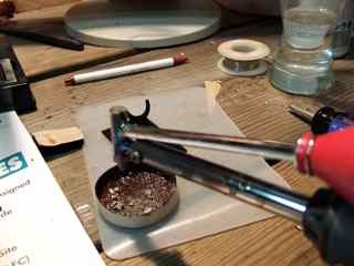
A desoldering iron is handy here, i would suggest getting one especially when getting to the op Amp removal.
Desoldering power rail cap
It is very important when using the desoldering iron after each use to expel any molten solder as to
not spray it all over the board when moving on to the next pin removal.
Expeling solder
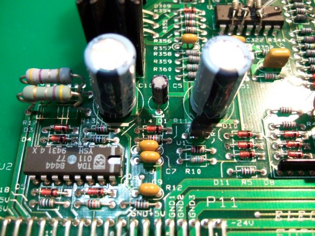
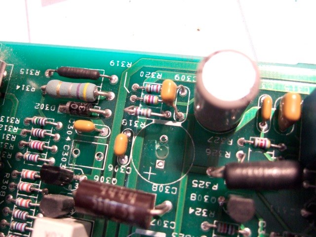
Working on the power supply area first. Replace C5 and C10 with same value (470uf) higher voltage
caps low esr caps would be a good choice but not mandatory.
Power rail caps to replace
I also decided after doing this to my Vim And CLM to add inductors to the same rails
just incase any unwanted noise is lurking about. I used 220uh indictors, Make sure
they are at least 3 amp rated, 1031 pointed that out to me after he measured the
current on those rails, you need to lift the one end of the resistors and add the inductors .
Location of resistors to lift
Newer beefier 270uf high current inductors
 [/url] [/url]
Edit: Added mod to +/- 24 volt rails
I decided to go ahead and add inductors to the +/- 24 volt rails, this requires cutting the
trace and scratching two locations on either side of trace to mount Big Beefy 270uf inductor.
Cut and scratched trace - 24 volt do the same further up the trace for +24 volt

Now add inductors to scratched trace areas here are both inductors in place. You may want to
hot glue the inductors in place so they don't accidentally rip the trace out if bumped while
removing a a later time for any other maintenance.
Inductors on +/- 24 volt rails

Athanasios
_________________
Don't blame your underwear for your crooked ass~ unknown Greek philosopher
"Republicans believe every day is the Fourth of July, but the Democrats believe every day is April 15." --- President Reagan
One Smart Dog!!!
Marquee High Performance Bellows now shipping!!
Marquee Modifications and Performance Enhancement
Marquee C-element and Bellow removal
Last edited by Nashou66 on Mon Nov 18, 2013 3:23 am; edited 7 times in total
|
|
| Back to top |
|
|
Nashou66
Joined: 12 Jan 2007
Posts: 16171
Location: West Seneca NY
|
| Link Posted: Thu Mar 13, 2008 1:24 am Post subject: Focus Board upgrades Part 2 |
|
|
Next we are going to replace 4 caps for each color for a total of 12. this I got from an old post By Chris Johnson and from the jeahong_lee thread were Mcpherv changed out some of the same caps that CJ changed. CJ's link is gone so i cant go back to explain what he wrote about this mod. From Mcpherv's comments the 6 1uf or 22uf caps ,depending on which board you have, couple the dynamic focus output and should be fairly important. I used 22uf caps to replace the older boards 1uf go with a higher voltage than 50 and low ESR like the panasonic FC series. I always do one section(color) at a time and test the board after each change incase I goof and something doesn't work it's a lot easier to track down a bad solder or backwards placed cap....having said that, on the newer boards caps C102,103,202,203,302,and 303 are marked for their polarity on the older boards they are not and I had to find out the polarity. the pics here are from the older board. so in this pic the positive side of the 22uf cap will go to the wider trace or the one farthest from the heat sink on the back of the board. And we will replace the 6 470uf 35v caps with 1000uf 35 or 50 v caps.These decouple the 24volt rails and half of the dynamic focus circuit. C108,208,308,107,207,307.
Removed caps 308 and 303
Caps 302,303,307,and 308 in place

close up

Now test the section you changed by ramping the focus up and down making sure it functions properly. If all is well do the other colors in the same manner.
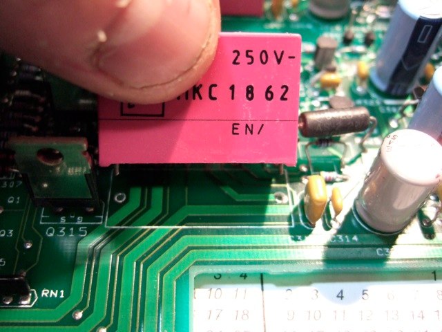
Another section of the dynamic focus are coupled by C120,220, and 320. these are 2.2uf 250v caps . Replace with same value higher voltage caps of same type. I went with 305 volt.EDIT 11/17/2013:Wima Caps would be even better
removing cap
New cap in place

once again test after change this time you can test after all three are swapped out.
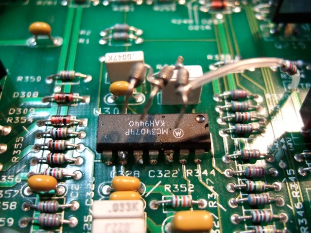
Next are the op amps u101,201 and 301 they will either be MC34074 or MC34084. these are noisy and distortive. Idealy I wanted to replace them with the OPA4134 but they no longer come in the DIP package so i found the TLE2074 which is less noisy and distortive. these can be gotten from Texas Instruments as free samples.
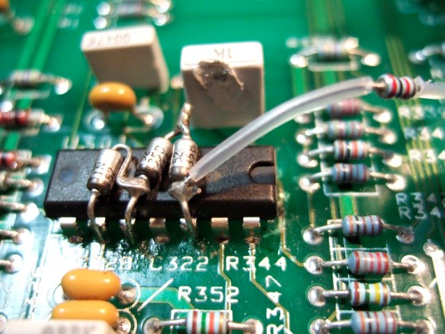
Now if you have a newer board you may not see the added diodes to the op amp as in my photos. I also decided to swap over the tech note diodes to the TLE2074's incase they do something else beside protect the op amp.
Op amp with Diodes
Removing Diode assembly from op amp
Now you need to remove the solder from underneath, i used the desoldering Iron, if you cant get it all out you will need to use some desoldering braid as well.
Underside of op amp section

After you remove as much of the solder as possible you may have to use a screwdriver or an exacto knive as i have to push any pins away from any remaining solder in the through holes.

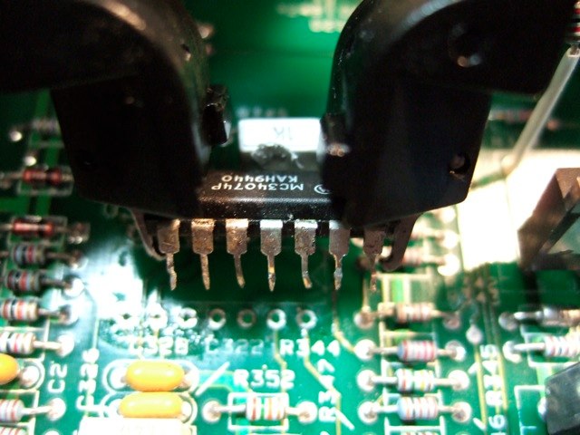
Now is the hard part, you dont want to pull any of the through hole or traces out from the board so begin loosening the chip slowly from the board i use a flat screwdriver to wiggle it loose then a IC puller while wiggling it. you may have to use your free hand to touch your soldering iron to the underside of any stuck pin while holding the board vertically and pulling on the chip from the top side, this takes practice but if you have a vice to hold the board its much easier.
IC puller
then place new chip into through holes make sure all solder is out or it will be almost impossible to place new chip, I put one side in then use a very small flat head screw driver to push each pin towards its appropriate hole.
New chip in place

now if you have the resistor assembly replace that to chip.Be carfull when removing that chip you can see in this next pic where i melted a cap with the iron!!!!
replacing Diode assembly
Now solder from underneath and test after each op amp removal as stated before.
that completes the focus board.
Athanasios
_________________
Don't blame your underwear for your crooked ass~ unknown Greek philosopher
"Republicans believe every day is the Fourth of July, but the Democrats believe every day is April 15." --- President Reagan
One Smart Dog!!!
Marquee High Performance Bellows now shipping!!
Marquee Modifications and Performance Enhancement
Marquee C-element and Bellow removal
Last edited by Nashou66 on Mon Nov 18, 2013 3:40 am; edited 3 times in total
|
|
| Back to top |
|
|
Joust

Joined: 05 May 2006
Posts: 2431
Location: Almonte, Ontario, Canada
TV/Projector: Marquee 8501LC
|
| Link Posted: Thu Mar 13, 2008 1:26 am Post subject: |
|
|
go git 'em Athanasios
|
|
| Back to top |
|
|
Nashou66
Joined: 12 Jan 2007
Posts: 16171
Location: West Seneca NY
|
|
| Back to top |
|
|
Joust
Joined: 05 May 2006
Posts: 2431
Location: Almonte, Ontario, Canada
TV/Projector: Marquee 8501LC
|
| Link Posted: Thu Mar 13, 2008 1:44 am Post subject: |
|
|
|
Mikes been pretty quiet around here lately. Maybe this will lure him out and he can add a tidbit or two.
|
|
| Back to top |
|
|
Nashou66
Joined: 12 Jan 2007
Posts: 16171
Location: West Seneca NY
|
| Link Posted: Thu Mar 13, 2008 1:56 am Post subject: |
|
|
| Joust wrote: | | Mikes been pretty quiet around here lately. Maybe this will lure him out and he can add a tidbit or two. |
He's probably very busy with the Barco and G90 mods. I hope he dosen't ask me any
technical questions! I just found all this stuff and tried it out on my own. I have read
up on a lot of the stuff and am trying to learn . Sooo many people here and on AVS
have helped me in understanding how CRT's work and also the electronics involved.
This hobby has truly become an addiction for me and I LOVE IT!!!!
Athanasios
_________________
Don't blame your underwear for your crooked ass~ unknown Greek philosopher
"Republicans believe every day is the Fourth of July, but the Democrats believe every day is April 15." --- President Reagan
One Smart Dog!!!
Marquee High Performance Bellows now shipping!!
Marquee Modifications and Performance Enhancement
Marquee C-element and Bellow removal
|
|
| Back to top |
|
|
Nashou66
Joined: 12 Jan 2007
Posts: 16171
Location: West Seneca NY
|
|
| Back to top |
|
|
Joust
Joined: 05 May 2006
Posts: 2431
Location: Almonte, Ontario, Canada
TV/Projector: Marquee 8501LC
|
| Link Posted: Thu Mar 13, 2008 2:50 am Post subject: |
|
|
can you take a close up picture of the area.
I have done that.
I have a board handy, I could add an inductor and take a picture for you.
i think i have a Ferrite kit i could use.
|
|
| Back to top |
|
|
Nashou66
Joined: 12 Jan 2007
Posts: 16171
Location: West Seneca NY
|
| Link Posted: Thu Mar 13, 2008 3:00 am Post subject: |
|
|
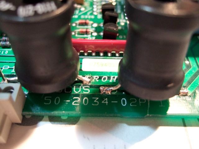
its in this picture of the power supply decoupling. the two pins on the right. you can see the
one trace has -24 the one below it is the +24 rail.

I was just thinking that the trace is very wide so I would have to bend the lead that will connect to
that cut rail and set it perpendicular so it goes across the whole width of the trace or wont it matter much and just use lots of solder?
Athanasios
_________________
Don't blame your underwear for your crooked ass~ unknown Greek philosopher
"Republicans believe every day is the Fourth of July, but the Democrats believe every day is April 15." --- President Reagan
One Smart Dog!!!
Marquee High Performance Bellows now shipping!!
Marquee Modifications and Performance Enhancement
Marquee C-element and Bellow removal
Last edited by Nashou66 on Fri Oct 29, 2010 4:41 pm; edited 2 times in total
|
|
| Back to top |
|
|
Nashou66
Joined: 12 Jan 2007
Posts: 16171
Location: West Seneca NY
|
| Link Posted: Thu Mar 13, 2008 3:05 am Post subject: |
|
|
Those traces go to the caps we replaced , through a resistor. I think its a 1 ohm resistor i dont have the board here
in front of me I have some color wheel inductors that i wanted to replace that resistor with. but none I have measured have a 1 ohm resistance the closest was a 100uh at .7ohm,s I dont think that would hurt anything being off by 3 tenths of an ohm.
Athanasios
_________________
Don't blame your underwear for your crooked ass~ unknown Greek philosopher
"Republicans believe every day is the Fourth of July, but the Democrats believe every day is April 15." --- President Reagan
One Smart Dog!!!
Marquee High Performance Bellows now shipping!!
Marquee Modifications and Performance Enhancement
Marquee C-element and Bellow removal
Last edited by Nashou66 on Thu Mar 13, 2008 6:40 pm; edited 1 time in total
|
|
| Back to top |
|
|
JustGreg
Joined: 07 Mar 2006
Posts: 3098
Location: Kenosha, WI
|
| Link Posted: Thu Mar 13, 2008 3:11 am Post subject: |
|
|
Stupid question time...what is an inductor and why would adding it to the chain help? 
If we're going to discuss some enhancement mods perhaps without writing a book you could throw in some 'theory/reasons for' along the way guys? I'm about as sharp as a wet Que-tip on alot of this and it would be great to learn more than how to follow the setup procedure and watch movies. Yes? No?
Greg
|
|
| Back to top |
|
|
Joust
Joined: 05 May 2006
Posts: 2431
Location: Almonte, Ontario, Canada
TV/Projector: Marquee 8501LC
|
| Link Posted: Thu Mar 13, 2008 3:13 am Post subject: |
|
|
we can add inductors easily. We can either cut the trace and use the inductor to jumper the gap. Or
Cut the trace and use the inductor to connect the pins to the resistor. I'd have to look at the spacing to give a proper assessment.
I've often scrapped the green soldermask off the trace and lay a lead on it and solder it. lay the lead parallel to the trace and solder at least a 1/2" of lead along the trace. the more the better for stability. If there is nothing on the other side of the board you could drill a hole and mount the inductor in them.
|
|
| Back to top |
|
|
Nashou66
Joined: 12 Jan 2007
Posts: 16171
Location: West Seneca NY
|
| Link Posted: Thu Mar 13, 2008 3:17 am Post subject: |
|
|
| JustGreg wrote: | Stupid question time...what is an inductor and why would adding
it to the chain help? If we're going to discuss some enhancement mods perhaps
without writing a book you could throw in some 'theory/reasons for' along the way guys?
I'm about as sharp as a wet Que-tip on alot of this and it would be great to learn more than
how to follow the setup procedure and watch movies. Yes? No?
Greg |
I got the Idea of using Inductors from a post on AVS by Mike parker. An inductor is a coil
wrapped around usually a ferrite material. This chokes out any noise that might be present
in the power line , and you want to use it on both the incoming and out
going rails. In Mike's thread on" VIM 02 Succes" he uses them on the CLM rails to clean them up.
hope that helps
Athanasios
_________________
Don't blame your underwear for your crooked ass~ unknown Greek philosopher
"Republicans believe every day is the Fourth of July, but the Democrats believe every day is April 15." --- President Reagan
One Smart Dog!!!
Marquee High Performance Bellows now shipping!!
Marquee Modifications and Performance Enhancement
Marquee C-element and Bellow removal
Last edited by Nashou66 on Thu Mar 13, 2008 6:42 pm; edited 1 time in total
|
|
| Back to top |
|
|
Nashou66
Joined: 12 Jan 2007
Posts: 16171
Location: West Seneca NY
|
| Link Posted: Thu Mar 13, 2008 3:20 am Post subject: |
|
|
| Joust wrote: | we can add inductors easily. We can either cut the trace and use the inductor to jumper the gap. Or
Cut the trace and use the inductor to connect the pins to the resistor. I'd have to look at the spacing to give a proper assessment.
I've often scrapped the green soldermask off the trace and lay a lead on it and solder it. lay the lead parallel to the trace and solder at least a 1/2" of lead along the trace. the more the better for stability. If there is nothing on the other side of the board you could drill a hole and mount the inductor in them. |
I have some huge 270uh indutors i got by mistake that i was going to use on my VIM but they are too large to fit, they should work great for these 24 volt rails.
Athansios
_________________
Don't blame your underwear for your crooked ass~ unknown Greek philosopher
"Republicans believe every day is the Fourth of July, but the Democrats believe every day is April 15." --- President Reagan
One Smart Dog!!!
Marquee High Performance Bellows now shipping!!
Marquee Modifications and Performance Enhancement
Marquee C-element and Bellow removal
Last edited by Nashou66 on Thu Mar 13, 2008 6:26 pm; edited 1 time in total
|
|
| Back to top |
|
|
JustGreg
Joined: 07 Mar 2006
Posts: 3098
Location: Kenosha, WI
|
| Link Posted: Thu Mar 13, 2008 3:47 pm Post subject: |
|
|
| Nashou66 wrote: | | JustGreg wrote: | Stupid question time...what is an inductor and why would adding
it to the chain help? If we're going to discuss some enhancement mods perhaps
without writing a book you could throw in some 'theory/reasons for' along the way guys?
I'm about as sharp as a wet Que-tip on alot of this and it would be great to learn more than
how to follow the setup procedure and watch movies. Yes? No?
Greg |
I got the Idea of using Inductors from a post on AVS by Mike parker. An inductor is a coil
wrapped around usually a ferrite material. This chokes out any noise that might be present
in the power line , and you want to use it on both the incoming and out
going rails. In mikes thread on VIM 02 success he uses them on the CLM rails to clean them up.
hope that helps
Athanasios |
That answered it perfectly.  I've seen the same things on wiring harnesses in copy machines and other electronic assemblies. They're usually encased in a snap shut plastic 'container'. I didn't know you could actually solder them across the legs of a component. Interesting. I'm working on cleaning up a spare room in my basement outside the HT in which I HOPE to get a nice little work station set up so I can begin going through the reams of mods/upgrades I've printed over the years. I've seen the same things on wiring harnesses in copy machines and other electronic assemblies. They're usually encased in a snap shut plastic 'container'. I didn't know you could actually solder them across the legs of a component. Interesting. I'm working on cleaning up a spare room in my basement outside the HT in which I HOPE to get a nice little work station set up so I can begin going through the reams of mods/upgrades I've printed over the years.
Thanks for the edjyamakashun. 
Greg
|
|
| Back to top |
|
|
1031
Joined: 22 Mar 2006
Posts: 657
Location: Finland
|
| Link Posted: Fri Mar 14, 2008 11:24 am Post subject: Re: Focus Board upgrades. |
|
|

Indutors in place

[/quote]
Athanasios. What is current rating of those inductors that you used?.
I tested yesterday that fcm takes about 0.2-0.8 amps, measured on just one rail, and it also take some "current spikes" so those inductors must have big enought to hadle that current. I think that inductor in that place must have current rating near 1,5-2amp min.
Also i think that changing those plactic caps doesent help anything, those are for "resonant circuit" different size caps are selected for different scanning freq. Those has nothing to do with noise..But those 3 100uF bipolars can make some drifting, changing those could help little for more stable focusing.
_________________
Marquee 9500LC (Frankenyokes / Thomas electric tubes / HD-10L / +many mod´s)
DVDO VP-50
New hobby, Rally
http://www.youtube.com/watch?v=vX2Rtpr1njs
http://www.youtube.com/watch?v=6ZP9FEFXV5c
http://www.youtube.com/watch?v=j065vei6j6s
http://www.facebook.com/pages/JTS-Racing-team/204443719572685
|
|
| Back to top |
|
|
|
|