
|
 |
|
|
| View previous topic :: View next topic |
| Author |
Message |
thewolfman
Joined: 28 Mar 2011
Posts: 1311
Location: Sweden

|
 Link Posted: Tue May 24, 2016 7:18 pm Post subject: Link Posted: Tue May 24, 2016 7:18 pm Post subject: |
 |
|
| mp20748 wrote: | Posted is two shots directly (camera pointed in lens) into the RED CRT. The last shot shows what I'm putting into it.
1920X1440 75hz - 297Mhz
It looks much better looking directly into the CRT
Corner Shot into the CRT
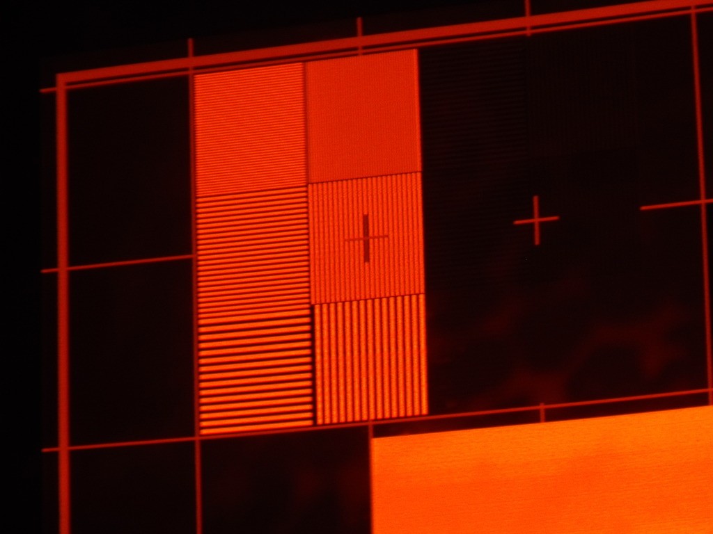
Center of the pattern
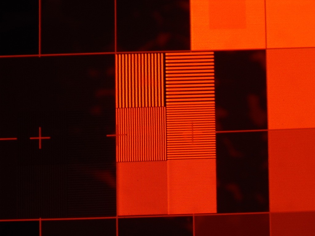
Scan rate and what's on the display of my pattern generator
 |
So Mike, I looked at my 297 MHz neck boards, serial number 50-2038-01p, and wonder if these images are from them? They aren't looking like these new styled VNB in this thread. Did I miss anything, weren't they suppose to be the new styled version?
Part number: 02-270338-01
|
|
| Back to top |
|
 |
cmjohnson
Joined: 03 Apr 2006
Posts: 5180
Location: Buried under G90s
|
| Link Posted: Tue May 24, 2016 8:29 pm Post subject: |
|
|
The neck boards you have (I have seen the pictures) are the "classic" 2038/2039 style cards which are the best type.
BTW, a 300 MHz dot clock translates to 150 MHz video bandwidth. The dot clock is ALWAYS twice the current bandwidth, at best.
A 297 MHz dot clock equals a video bandwidth of 148.5 MHz.
|
|
| Back to top |
|
|
mp20748

Joined: 12 Sep 2006
Posts: 5681
Location: Maryland
TV/Projector: 9500LC Ultra / Super 02 and 03 VIM
|
| Link Posted: Tue May 24, 2016 8:40 pm Post subject: |
|
|
Look at the eBay posting. It as well as the pictures show exactly what you have.
| thewolfman wrote: | | mp20748 wrote: | Posted is two shots directly (camera pointed in lens) into the RED CRT. The last shot shows what I'm putting into it.
1920X1440 75hz - 297Mhz
It looks much better looking directly into the CRT
Corner Shot into the CRT
Center of the pattern
Scan rate and what's on the display of my pattern generator
|
So Mike, I looked at my 297 MHz neck boards, serial number 50-2038-01p, and wonder if these images are from them? They aren't looking like these new styled VNB in this thread. Did I miss anything, weren't they suppose to be the new styled version?
Part number: 02-270338-01 |
|
|
| Back to top |
|
|
thewolfman
Joined: 28 Mar 2011
Posts: 1311
Location: Sweden
|
| Link Posted: Tue May 24, 2016 8:48 pm Post subject: |
|
|
Yes I noticed they are the same, I just wondered why they aren't the same as the VNB this topic is about, which had me believe it was about them. It doesn't matter, as long as I paid for your best parts and those straight out of your personal projector, your best work was the deal we made.
I'm installing them now anyways.
|
|
| Back to top |
|
|
cmjohnson
Joined: 03 Apr 2006
Posts: 5180
Location: Buried under G90s
|
| Link Posted: Tue May 24, 2016 10:05 pm Post subject: |
|
|
Wolfman, you HAVE Mike's best work. Unless he's modded a 2038 or 2039 card even further since he made those.
Let me state categorically, the "new" 0340 neck cards will NEVER, NEVER, NEVER match the performance of the 0338/0339 cards no matter what mods are done to them. They exist only because VDC could not GET the GOOD power transistors anymore.
The MRF 548/549 pair of power transistors is THEE SHIIT, the 2038/2039 neck cards are the BEST video neck card amps in the entire industry in STOCK form, and what Mike has done with them is frankly incredible.
But the 0340 and 81771 neck cards are different animals, designed as a way to keep Marquees in production and satisfy the needs of the simulator industry but NO MORE THAN THAT. They do not track greyscale as well at higher contrast levels and they certainly do not have the bandwidth. They're not bad cards but they are not in any way, shape, or form the equal of the "classic" 0338/0339 cards.
BTW, remember what I said earlier: Bandwidth is not more than HALF the pixel clock rate.
If you have a 300 MHz pixel clock, then video bandwidth is not more than 150 MHz.
A 297 MHz video bandwidth would require a 594 MHz pixel clock. What even delivers that kind of pixel clock rate?
Even high end video cards only have 400 MHz RAMDACs. If they can be overclocked, maybe they might reach 500 MHz, but
that's a far cry from a 600 MHz pixel clock.
I know that there are certain versions of the QuantumData 802 series generator that can be equipped with a 600 MHz clock
gen option, for about 18,000 dollars. But in the real world, 200 MHz of real video bandwidth is all you're going to ever need
out of any source that you are likely to encounter.
Do. Not. Mistake. Pixel. Clock. For. Video. Bandwidth.
|
|
| Back to top |
|
|
thewolfman
Joined: 28 Mar 2011
Posts: 1311
Location: Sweden
|
| Link Posted: Tue May 24, 2016 11:04 pm Post subject: |
|
|
Yes, I know about the Motorola thing, so I'm comfortable with the old style version, but I hate loose ends and I wanted to clear things so I know what's what. And I did try them on, with my moome V1, and it went to sh*t immediately. Many strange things happened, and will make no other attempt at it until my modded V3 gets here, because that one behaves totally different.
Tonight I just experienced messed up signals that went and came, it has in the past too so no use in trying. In the end it said I had no Interface installed and half the menus were missing. Letters that were dim but borders bright, stuff like that. But I was expecting it to act up so no surprise there.
|
|
| Back to top |
|
|
greg9518lc
Joined: 19 Apr 2016
Posts: 360
|
| Link Posted: Wed May 25, 2016 1:55 pm Post subject: |
|
|
not
_________________
VDC 9518LC modded: I do not sell or promote mods only interested in the best PQ possible......
Last edited by greg9518lc on Wed Jul 13, 2016 7:30 pm; edited 2 times in total
|
|
| Back to top |
|
|
thewolfman
Joined: 28 Mar 2011
Posts: 1311
Location: Sweden
|
| Link Posted: Wed May 25, 2016 2:02 pm Post subject: |
|
|
| greg9518lc wrote: | | thewolfman wrote: | Yes, I know about the Motorola thing, so I'm comfortable with the old style version, but I hate loose ends and I wanted to clear things so I know what's what. And I did try them on, with my moome V1, and it went to sh*t immediately. Many strange things happened, and will make no other attempt at it until my modded V3 gets here, because that one behaves totally different.
Tonight I just experienced messed up signals that went and came, it has in the past too so no use in trying. In the end it said I had no Interface installed and half the menus were missing. Letters that were dim but borders bright, stuff like that. But I was expecting it to act up so no surprise there. |
? why would you expect it to act up? Your right those old cards are the bomb. Very clean and transparent. |
Because the moome V1 gave this odd dual color on letters when I used it with my modded VIM 03 way back, but now it's unusable for at least these new boards. But ones I installed the new moome V3 back then the colors got sorted.
|
|
| Back to top |
|
|
greg9518lc
Joined: 19 Apr 2016
Posts: 360
|
| Link Posted: Wed May 25, 2016 2:14 pm Post subject: |
|
|
Because the moome V1 gave this odd dual color on letters when I used it with my modded VIM 03 way back, but now it's unusable for at least these new boards. But ones I installed the new moome V3 back then the colors got sorted.[/quote]
Thats good so you are progressing forward it sounds like?
_________________
VDC 9518LC modded: I do not sell or promote mods only interested in the best PQ possible......
|
|
| Back to top |
|
|
thewolfman
Joined: 28 Mar 2011
Posts: 1311
Location: Sweden
|
| Link Posted: Wed May 25, 2016 2:33 pm Post subject: |
|
|
Not at all, this is a disaster so far. But the pc acted up a bit too, from removing and installing the HDMI-cords going to the monitor and pj, and at some point I was all off a sudden running 75Hz when it's setup for 72Hz. Many weird things happening so no use in trying anymore, I'll wait for my modded moome V3 to get back and try some more then. I'm afraid of spot burning if I interchange boards, like the CLM I tried one time, which made no change at all btw, only different shape of the width a bit.
Got to go for a while.
|
|
| Back to top |
|
|
cmjohnson
Joined: 03 Apr 2006
Posts: 5180
Location: Buried under G90s
|
| Link Posted: Wed May 25, 2016 2:48 pm Post subject: |
|
|
Spot burning is nearly impossible in a Marquee. (Nearly. You can do it if you lose G2 control and shut down the projector in that condition. If the screen ever goes FULL bright and you see retrace lines, pull P14 and wait for it to go dark before shutting down the projector. )
Spot burns can only happen in the event of complete loss of deflection while beam current is running.
The HDM and the G2 systems are the only things that can cause a spot burn via failure.
Which is unlikely.
As I understand it, the Marquee has the best protection against spot burns of any projector ever made except for possibly
the Evans & Sutherland ESCP 2000 raster/calligraphic projector, and you aren't going to be using one of those in a home theater environment. They're something north of 100K anyway.
|
|
| Back to top |
|
|
thewolfman
Joined: 28 Mar 2011
Posts: 1311
Location: Sweden
|
| Link Posted: Wed May 25, 2016 4:44 pm Post subject: |
|
|
I ramped up contrast at one point, because its sort of dim in an odd way, and when I hit 100 it immediately kick in some protection mode and became dim(er) and then I pulled the P14 and turned it off. I then turned it on again and nothing changed it and was like it was before I ramped up contrast. So nothing came out of that, I didn't damage it.
But I must get hold of a blu-ray player and feed it Baraca at 60 Hz and see. I wasn't expecting it to be plug and play just yet but in for a little work with maybe trying some alternative CLM perhaps. We both have a late VDC 2010/2011 machines so what are the odds they could be different then..? No, mine had LUGs on it too from the beginning and thinks he had them too, not sure they were tested as LCP ones they were converted into LCP+LUGs. But my other modded LCP VNB worked just fine with my stock moome V3 but never tried them with my moome V1.. I guess I could try that + newly modded VIM 02.
I have a modded VIM 03 too (my old one) and I could try that as well.. we'll see when I work up my mood for it.
|
|
| Back to top |
|
|
cmjohnson
Joined: 03 Apr 2006
Posts: 5180
Location: Buried under G90s
|
| Link Posted: Wed May 25, 2016 5:17 pm Post subject: |
|
|
What you encountered was the beam current limiter circuit kicking in. It's there specifically to protect the tube in the event that for any reason contrast goes too high for too long.
It is adjustable. There is a current limiter adjustment pot on each neck card. Usually it's covered in grey epoxy to keep you from messing with it, once it's preset at the factory.
Mike can tell you more about it than I can but as I BELIEVE it to be, it is set so that it will trigger after a few seconds on a full white field with contrast at 100. So you create those conditions and turn the pot until it triggers. After setting the pot, ramp the contrast back down and take it up by 10 steps at a time to be sure it doesn't trigger below a contrast level of 90. You can then make small adjustments to ensure that it triggers between 95 and 100.
Really, it SHOULD trigger before contrast reaches 100. There is NO reason to run the tubes that hard, you can't really see the
difference in brightness anyway, but you sure will lose resolution when you drive it that hard. No matter how good your neck cards and focus yokes are, when you run it that hard, the beam profile will spread due to the fact that the beam energy distribution pattern is a Gaussian profile and the harder you drive it, the more the beam effective diameter increases.
It's like taking slices out of a cone. The lower down you slice, the bigger the circle of the sliced section.
|
|
| Back to top |
|
|
thewolfman
Joined: 28 Mar 2011
Posts: 1311
Location: Sweden
|
| Link Posted: Wed May 25, 2016 5:30 pm Post subject: |
|
|
|
Nah, I don't want to muck around with pots for current limiter, unless all else fails and I'm forced to learn about it, and before sending it all back for an overlook. The best thing would be for MP to get himself a HTPC at 800p and do testing with that resolution as well before sending stuff out, it is a small cost and it would makes things easier than shipping stuff back and forth.
|
|
| Back to top |
|
|
greg9518lc
Joined: 19 Apr 2016
Posts: 360
|
| Link Posted: Wed May 25, 2016 7:33 pm Post subject: |
|
|
| thewolfman wrote: | | Nah, I don't want to muck around with pots for current limiter, unless all else fails and I'm forced to learn about it, and before sending it all back for an overlook. The best thing would be for MP to get himself a HTPC at 800p and do testing with that resolution as well before sending stuff out, it is a small cost and it would makes things easier than shipping stuff back and forth. |
You should work something out with Kurt and get it all sorted out or at least pm him there should be no reason to send them
back again and the mods you have he has run 800p 96hz with no issues. Just a thought?
_________________
VDC 9518LC modded: I do not sell or promote mods only interested in the best PQ possible......
|
|
| Back to top |
|
|
thewolfman
Joined: 28 Mar 2011
Posts: 1311
Location: Sweden
|
| Link Posted: Wed May 25, 2016 7:53 pm Post subject: |
|
|
| greg9518lc wrote: | | thewolfman wrote: | | Nah, I don't want to muck around with pots for current limiter, unless all else fails and I'm forced to learn about it, and before sending it all back for an overlook. The best thing would be for MP to get himself a HTPC at 800p and do testing with that resolution as well before sending stuff out, it is a small cost and it would makes things easier than shipping stuff back and forth. |
You should work something out with Kurt and get it all sorted out or at least pm him there should be no reason to send them
back again and the mods you have he has run 800p 96hz with no issues. Just a thought? |
Great thought, but 800p 96Hz I have already tried, and there is nothing special about that, Marquee can handle that fine. But timings, matched with mine, would have helped a lot too tune in on my gear in advance. Just to be on the safe side.
Never mind, it will solve itself soon enough.
|
|
| Back to top |
|
|
mp20748
Joined: 12 Sep 2006
Posts: 5681
Location: Maryland
TV/Projector: 9500LC Ultra / Super 02 and 03 VIM
|
| Link Posted: Wed May 25, 2016 8:09 pm Post subject: |
|
|
This is very similar to the problems you were having before you got the later version Moome card.
But regardless, the section of any of those boards that has been modified or changes made to it has nothing to do with any of the sync or timing circuits. Only the video section was modified to include the supply rails to the video circuit, so in no way could any of the things you listed be related to the video section of the boards.
What happens when you bring up the internal test pattern, are you seeing everything as it should be?
Also, those boards were the same set that was in my Marquee. They were tested on a many scan rate, that is how I check the boards in the process to make you they are stable from one scan rate to the other.
This is not the right thread for those neck boards, a thread has not been created that deals with them. they would be more of in the 250mhz range (as shown in the listing). These are dialed down a bit for better noise performance (low end - black level)
|
|
| Back to top |
|
|
gjaky
Joined: 05 Jun 2010
Posts: 2790
Location: Budapest, Hungary
|
| Link Posted: Tue Nov 01, 2016 4:43 pm Post subject: |
|
|
I am now playing with a set of these new VDC neckboards too. It is interesting... In its stock form the output waveform is quite under compensated. The oscilloscope measurements are not very promising either, there seems to be an odd assymetry in the output signal between G1 and Cathode drive level (G1 can go beyond 40Vpp, the Cathode drive barely reaches 30Vpp). Furthermore the fastest rise time at the output is around 7ns (~50MHz real bandwidt) and is more or less independent of drive level (ie. this does not get better at lower levels either). For proper comparison, an old style Marquee neckboard has a rise time around 3.5ns at similar conditions, while my old M9000 neckboard has around 4ns rise time. a VPA13 (130MHz advertised bandwidth) also has around 3.5ns rise time.
I've went a little deeper in analyzing this circuit.
Despite the output seems to be under compensated the opamp input stage generates an enormous ammount of overshoot to the input signal, with the intention to cancel out the lower speed of the output, with little success...
It is widely spread theory that these VDC neckboards could not perform as good as the old VNB-s because the Motorola transistors were far superior (1.4GHz vs. 500MHz) than the Sanyo transistor those are used on the VDC boards. While this might be true this is not the main reason as I see.
For example I changed Q21 and Q17 transitors to BFQ262, and BFQ252 those are comparable to the original Motorola transistors (~1.4GHz) but has the same package and pinout as the Sanyo transistors, so changing these transistors did not bring any significant bandwidth improvement. I also changed Q19 to BFG135 (which is a 7GHz transistor), this also did not yeld anything worth noting.
-On the other hand tuning the coils L1 and L3 to 470uH brought a big improvement in the response even with the original transistors, so the rise time values got down to 5.2ns (with the input overshoot). But so far I could not find any way to go below 5ns rise time, so this seems to be some sort of performance barrier.
-With the tuned coils, but the bypassed input oversoot the rise time is again around 8ns.
-With the tuned coils and bypassed input oversoot, but increased C6 (->200pF, emitter peaking cap) the rise time is around 6ns.
-Combining all the available peaking will increase overshoot and ringing to an unfavourable level, without getting the rise time below the already mentioned 5.2ns barrier.
There is one other odd thing, the diodes on the output D11 and D12. I'm not exactly familiar with their purpose I did not see similar on any other neckboards, probably they help in arc protection. The diodes are seemingly reverse biased, especially D12.The boards I have here have an added resistor that is connecting D12's anode to the +85V supply giving some sort of forward biasing to it, regardless the mentioned assymetry in the output signal is exactly caused by D12, replacing this diode with a short the symmetry on the output restores. But it may have adverse effect on the board's reliability, I tested only on benc so far without that diode.
| Description: |
| Rise time on G1 output, 1ns/div horizontal. |
|
| Filesize: |
26.74 KB |
| Viewed: |
8204 Time(s) |

|
| Description: |
| G1 output on the VDC VNB, 10V/div vertical 20ns/div horizontal. After coil modifications, BFQ252/262 transistors, and input overshoot left intact. |
|
| Filesize: |
26.97 KB |
| Viewed: |
8204 Time(s) |

|
| Description: |
| Output of the HFA1100 on the VDC neckboard |
|
| Filesize: |
25.87 KB |
| Viewed: |
8204 Time(s) |

|
_________________
projectors in the past : NEC 6-9PG xtra, Electrohome Marquee 6-7500, NEC XG 1351 LC ( with super modified Electrohome VNB neckboard !!!)
current: VDC Marquee 9500LC
The MOD: VNB-DB, VIM-DB
|
|
| Back to top |
|
|
greg9518lc
Joined: 19 Apr 2016
Posts: 360
|
| Link Posted: Tue Nov 01, 2016 7:23 pm Post subject: |
|
|
Nice work hope you find a solution
_________________
VDC 9518LC modded: I do not sell or promote mods only interested in the best PQ possible......
|
|
| Back to top |
|
|
greg9518lc
Joined: 19 Apr 2016
Posts: 360
|
| Link Posted: Sun Nov 06, 2016 5:08 am Post subject: |
|
|
Nice to hear Gijaky you have solved the hiccups look forward to the finished product as it is clearly a step in a better direction. Count me in for a set when the project is finalized.
_________________
VDC 9518LC modded: I do not sell or promote mods only interested in the best PQ possible......
|
|
| Back to top |
|
|
|
|
|
|
|
|
You cannot post new topics in this forum
You cannot reply to topics in this forum
You cannot edit your posts in this forum
You cannot delete your posts in this forum
You cannot vote in polls in this forum
You cannot attach files in this forum
You can download files in this forum
|
Forum powered by phpBB © phpBB Group
|
|


