| View previous topic :: View next topic |
| Author |
Message |
Nashou66
Joined: 12 Jan 2007
Posts: 16171
Location: West Seneca NY

|
 Link Posted: Wed Dec 03, 2008 7:20 pm Post subject: Link Posted: Wed Dec 03, 2008 7:20 pm Post subject: |
 |
|
| Boilermaker wrote: | | Quote: | Isn't it selectable to either 120 input or 208 input
and the same for the output just depending on how you wire it up?
Also its three connected so each could be used separately right? |
Athanasios,
Depending on how it is configured, yes you can feed it either 208 single phase or 120 single phase. The 208/120 distribution systems used in hospitals is three phase with 208 volts phase to phase and 120 volts phase to neutral.
The secondary side will be 120 either way.
The pita is that in order to supply the full 15KVA, you would need about 125 amps at 120 volt.
But hey, who needs 15KVA, right?
Bob |
Right you don't need the full 15Kva so couldn't it be split up to three separate units?
Athanasios
_________________
Don't blame your underwear for your crooked ass~ unknown Greek philosopher
"Republicans believe every day is the Fourth of July, but the Democrats believe every day is April 15." --- President Reagan
One Smart Dog!!!
Marquee High Performance Bellows now shipping!!
Marquee Modifications and Performance Enhancement
Marquee C-element and Bellow removal
|
|
| Back to top |
|
 |
Boilermaker
Joined: 21 May 2006
Posts: 527
|
| Link Posted: Thu Dec 04, 2008 1:43 pm Post subject: |
|
|
| Quote: | | Right you don't need the full 15Kva so couldn't it be split up to three separate units? |
Yes.
|
|
| Back to top |
|
|
nomadII
Joined: 16 Jun 2006
Posts: 252
|
| Link Posted: Tue Dec 09, 2008 10:18 pm Post subject: |
|
|
|
Nicely done, now that is protection!!
|
|
| Back to top |
|
|
lovebohn
Joined: 16 Mar 2006
Posts: 181
Location: Wisconsin
|
| Link Posted: Mon Nov 09, 2009 8:26 pm Post subject: |
|
|
|
Has anyone found a nice used isolation transformer, I just can't find my hum problem and looks like this could help.
|
|
| Back to top |
|
|
lovebohn
Joined: 16 Mar 2006
Posts: 181
Location: Wisconsin
|
| Link Posted: Sun Jan 17, 2010 4:48 am Post subject: |
|
|
After getting some valuable assistance from Bob I was able to find a 10kva isolation transformer to use in my HT room. Here are a few screen shots of the wiring. Any advice on what wires i should use with the power feed (240v) from my main panel and then from there to the sub panel. I'm going to need to run through this tread again just to make sure I get the whole concept correct. I know the big thing is not having your neutral and ground on the same bus bar.
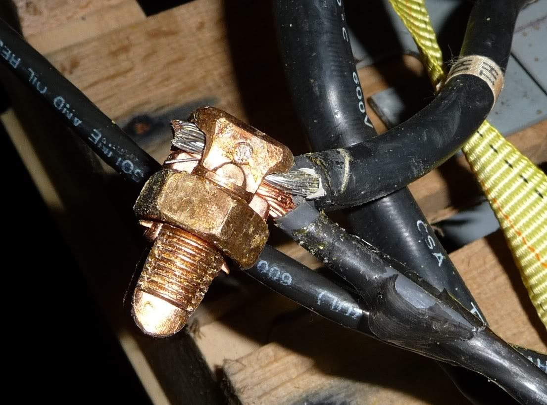
This is what came with the transformer connecting the wiring, that isn't what I imagined you should use or is it ok?
|
|
| Back to top |
|
|
macgyver655
Joined: 22 Aug 2007
Posts: 8508
|
| Link Posted: Sun Jan 17, 2010 6:18 am Post subject: |
|
|
|
A 10kva transformer draws 60 amps so you need a 60 amp breaker to feed it. If you run copper wire then 6 gauge is ok, 4 gauge is better. If you run aluminum wire it has to be 4 gauge.
|
|
| Back to top |
|
|
Nashou66
Joined: 12 Jan 2007
Posts: 16171
Location: West Seneca NY
|
| Link Posted: Sun Jan 17, 2010 6:39 am Post subject: |
|
|
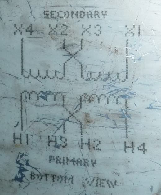
We need to see what each wire is labled. then off the table sticker it tells you what to jumper or in your case since there is no Block what to tie together.
So for the primary according to the table tie H1, H3 together and H2,H4 together if feeding it with a 120 volt line. But since you want 240 input it look like you tie H2 and H3 together and put one incoming line to H1 and the other to H4, both of these are 120 line form your 60 amp braker, get a 2 pole. Now you need a ground and the two hots going to your transformer. put the transformer as close to your sub panel as you can. Now ground the box of the trnsformer to the main panel box on the primary side.
Now for the secondary side to your sub panel.
Run a ground from the secondary side to your sub panel.
If you have a bonding screw, usually green remove it form the sub panel box.
Now for 120 tie X1 and X3 together, and tie X2 and X4 together.
Now take X1 to one side of your bus bar in the sub panel and X 4 to the other side.
Add some breakers and test with a multimeter if you have 120 volts on the beaker outs.
I am pretty sure this is how it should be done going from memory and re reading my install.
But Bob or another person should check my instructions before you go though it all.
Athanasios
_________________
Don't blame your underwear for your crooked ass~ unknown Greek philosopher
"Republicans believe every day is the Fourth of July, but the Democrats believe every day is April 15." --- President Reagan
One Smart Dog!!!
Marquee High Performance Bellows now shipping!!
Marquee Modifications and Performance Enhancement
Marquee C-element and Bellow removal
|
|
| Back to top |
|
|
macgyver655
Joined: 22 Aug 2007
Posts: 8508
|
| Link Posted: Sun Jan 17, 2010 6:46 am Post subject: |
|
|
| Nashou66 wrote: | .
Now for 120 tie X1 and X3 together, and tie X2 and X4 together.
Now take X1 to one side of your bus bar in the sub panel and X 4 to the other side.
|
I believe this part is incorrect but I'm to tired right now to verify. I'll recheck tomorrow.
|
|
| Back to top |
|
|
Nashou66
Joined: 12 Jan 2007
Posts: 16171
Location: West Seneca NY
|
| Link Posted: Sun Jan 17, 2010 6:52 am Post subject: |
|
|
| macgyver655 wrote: | | Nashou66 wrote: | .
Now for 120 tie X1 and X3 together, and tie X2 and X4 together.
Now take X1 to one side of your bus bar in the sub panel and X 4 to the other side.
|
I believe this part is incorrect but I'm to tired right now to verify. I'll recheck tomorrow. |
You Might be right, I am going off my install. His transformer is different and has no tie in bar to add jumpers.
I wonder if he could find a connection block like mine. it make it easier. Love bone also look to make sure each wire is labeled, i see one is in your pic, hopefully the rest will be also.
I'm tired too i have to work at 7am, off to bed.
Athanasios
_________________
Don't blame your underwear for your crooked ass~ unknown Greek philosopher
"Republicans believe every day is the Fourth of July, but the Democrats believe every day is April 15." --- President Reagan
One Smart Dog!!!
Marquee High Performance Bellows now shipping!!
Marquee Modifications and Performance Enhancement
Marquee C-element and Bellow removal
|
|
| Back to top |
|
|
lovebohn
Joined: 16 Mar 2006
Posts: 181
Location: Wisconsin
|
| Link Posted: Sun Jan 17, 2010 1:55 pm Post subject: |
|
|
| macgyver655 wrote: | | A 10kva transformer draws 60 amps so you need a 60 amp breaker to feed it. If you run copper wire then 6 gauge is ok, 4 gauge is better. If you run aluminum wire it has to be 4 gauge. |
I currently have copper 6 awg wire feeding the sub panel, I think its on a 50 amp breaker off the main panel.
|
|
| Back to top |
|
|
lovebohn
Joined: 16 Mar 2006
Posts: 181
Location: Wisconsin
|
| Link Posted: Sun Jan 17, 2010 2:04 pm Post subject: |
|
|
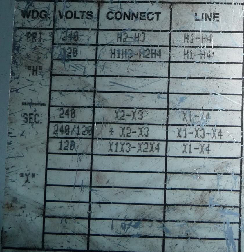
| Nashou66 wrote: | We need to see what each wire is labled. then off the table sticker it tells you what to jumper or in your case since there is no Block what to tie together.
So for the primary according to the table tie H1, H3 together and H2,H4 together if feeding it with a 120 volt line. But since you want 240 input it look like you tie H2 and H3 together and put one incoming line to H1 and the other to H4, both of these are 120 line form your 60 amp braker, get a 2 pole. Now you need a ground and the two hots going to your transformer. put the transformer as close to your sub panel as you can. Now ground the box of the trnsformer to the main panel box on the primary side. |
From a few other pictures i took, it looks like H2 & H3 are tied now and i assumed feeding the power on H1 & H4 was correct. My current 50 amp breaker is a two pole, I'm going to use that for now. I will use the one neutral/ground wire that currently goes to the sub panel for the transformer ground.
|
|
| Back to top |
|
|
lovebohn
Joined: 16 Mar 2006
Posts: 181
Location: Wisconsin
|
| Link Posted: Sun Jan 17, 2010 2:07 pm Post subject: |
|
|
| macgyver655 wrote: | | Nashou66 wrote: | .
Now for 120 tie X1 and X3 together, and tie X2 and X4 together.
Now take X1 to one side of your bus bar in the sub panel and X 4 to the other side.
|
I believe this part is incorrect but I'm to tired right now to verify. I'll recheck tomorrow. |
I was thinking we did the secondary part the same, tie x2 & x3 together and use x1 & x4 to feed the sub panel.
|
|
| Back to top |
|
|
Nashou66
Joined: 12 Jan 2007
Posts: 16171
Location: West Seneca NY
|
|
| Back to top |
|
|
Nashou66
Joined: 12 Jan 2007
Posts: 16171
Location: West Seneca NY
|
| Link Posted: Sun Jan 17, 2010 2:50 pm Post subject: |
|
|
No you do it the same way i first mentioned i am 99% sure, you tie the secondaries together and then go to the sub panel from on of each winding, X1 and X4 .
look at the first page of this thread and how Bob explained for mine to be hooked up, basicly the same with different numbers and in yours they just crossed the wires in the Diagram for ease of reading.
Athanasios
_________________
Don't blame your underwear for your crooked ass~ unknown Greek philosopher
"Republicans believe every day is the Fourth of July, but the Democrats believe every day is April 15." --- President Reagan
One Smart Dog!!!
Marquee High Performance Bellows now shipping!!
Marquee Modifications and Performance Enhancement
Marquee C-element and Bellow removal
|
|
| Back to top |
|
|
macgyver655
Joined: 22 Aug 2007
Posts: 8508
|
| Link Posted: Sun Jan 17, 2010 5:17 pm Post subject: |
|
|
|
If your going to run 240v to the sub panel, which you should, then you have to tie X2 and X3 together. This is also where you connect your neutral line to the sub panel. X1 and X4 are the 2 hot lines to the sub panel. Gnd would be to case gnd. Personally I would run the sub panel gnd out to its own ground rod. Then your sub panel would be totally isolated.
|
|
| Back to top |
|
|
Nashou66
Joined: 12 Jan 2007
Posts: 16171
Location: West Seneca NY
|
| Link Posted: Sun Jan 17, 2010 5:32 pm Post subject: |
|
|
But to make this an Isolation transformer you would not run a neutral mac youd only run two hots like i did , read the first page of this thread. I have two 120 lines coming into my sub panel, no nuetral and the Ground. In the Sub panel i removed the Bonding screw from the Buss bar. so the ground is separate.
From his main panel box you'd run no nuetral.
Unless your calling the one Hot a neutral just to keep things easy.
I now think he was right from his first assessment, tie x2 and x3 together and run X1 to one side and use X4 as the so called "neutral even though Just another Hot.
Here is a link:
http://www.etechvideo.com/techtip10.htm
| Quote: | 2 - [b]You will need just two conductors plus ground from your main panel. A neutral conductor is not used. If your cable already has a neutral, just wirenut it off at both ends.
3 - These two wires will attach to terminals #1 and #8 at your transformer. It doesn't matter which one is which. I see that the "primary input" label on your transformer calls terminal #8 neutral. Ignore this for your application. Both wires are "Lines" and have 240 volts potential between them.
4 - The ground wire from your main panel will attach to the ground screw on the transformer box which should be bonded with the chassis. There will be others attached to this ground also, so it might be easier to pick up a little ground bar at an supply house or Lowes.
5 - Attach a jumper between terminals #4 and #5 at your xfmr. This will set it up for 240 volts input. We could have wired it for 120volt input, but this would present an unbalanced load to your main panel which is not good practice.
6 - Attach a jumper between terminals #9 and #11 and between terminals #10 and #12. Notice that while the primaries are wired in series, the secondaries are wired in parallel. This way there are twice as many primary windings as are in the secondary. This "ratio" is what determines the ratio of input voltage to output voltage - 240/120.
[/b] |
Corresponding pic of mine:

His for comparison
Athanasios
_________________
Don't blame your underwear for your crooked ass~ unknown Greek philosopher
"Republicans believe every day is the Fourth of July, but the Democrats believe every day is April 15." --- President Reagan
One Smart Dog!!!
Marquee High Performance Bellows now shipping!!
Marquee Modifications and Performance Enhancement
Marquee C-element and Bellow removal
|
|
| Back to top |
|
|
macgyver655
Joined: 22 Aug 2007
Posts: 8508
|
| Link Posted: Sun Jan 17, 2010 5:42 pm Post subject: |
|
|
If you have your output configured to 120v then 1 line is hot and 1 line is neutral. A neutral would never go to a hot buss. It goes to the neutral buss. You would have to jumper the hot to the other hot buss in the panel. This would result in less current available from the xformer. Plus you would never have 240V available at the sub panel if you needed it.
You dont need a neutral to the primary side for the coil to develop the field but you need a neutral on the secondary side for the panel.
|
|
| Back to top |
|
|
lovebohn
Joined: 16 Mar 2006
Posts: 181
Location: Wisconsin
|
| Link Posted: Sun Jan 17, 2010 6:54 pm Post subject: |
|
|
|
I'll snap a few pictures of how it was wired from the former owner, in some ways i feel both of you are correct.
|
|
| Back to top |
|
|
Nashou66
Joined: 12 Jan 2007
Posts: 16171
Location: West Seneca NY
|
| Link Posted: Sun Jan 17, 2010 6:59 pm Post subject: |
|
|
Mac on mine I do have the Jumper in the panel box. I did that to get the most Amps, with a 240 input to my sub the amps went down to 20 with 120 its at about 42 amps.

In this next pic(before i added the Iso) I do not have the Green screw in place, i jumped the left black over to where the other black wire is. from the ISo secondary side terminal 9. Terminal 10 i sent to the neutral bar. this isolates the hot from the ground.

I get 120 Volts on all breakers and I can even grab the Ground and touch the hot not get a shock.
Athanasios
_________________
Don't blame your underwear for your crooked ass~ unknown Greek philosopher
"Republicans believe every day is the Fourth of July, but the Democrats believe every day is April 15." --- President Reagan
One Smart Dog!!!
Marquee High Performance Bellows now shipping!!
Marquee Modifications and Performance Enhancement
Marquee C-element and Bellow removal
|
|
| Back to top |
|
|
macgyver655
Joined: 22 Aug 2007
Posts: 8508
|
| Link Posted: Sun Jan 17, 2010 7:18 pm Post subject: |
|
|
A: That 20.83a rating is for each 120v line that develops the 240v. The math come out the same but the line size changes which should yield more current.
B: You can never connect a 240v device when wired your way. If you never plan on having a 240v device then you could wire it differently.
C: Jumping a hot line to power the other hot buss will work but will never pass code. Plus its not the right thing to do.
D: The reason for (2) 120v coils is if you wanted to connect each one to an individual 120v socket, then connect each to whatever. You could also connect each coil in parallel to increase the 120v current. Not for connection to a panel box. To the panel box it should be connected via 240v.
|
|
| Back to top |
|
|
|
|


