| View previous topic :: View next topic |
| Author |
Message |
jgrice53
Joined: 10 Dec 2014
Posts: 165
Location: marion, sc 29571

|
 Link Posted: Thu Dec 18, 2014 4:43 pm Post subject: Link Posted: Thu Dec 18, 2014 4:43 pm Post subject: |
 |
|
|
yes
|
|
| Back to top |
|
 |
macgyver655
Joined: 22 Aug 2007
Posts: 8508
|
| Link Posted: Thu Dec 18, 2014 4:49 pm Post subject: |
|
|
| jgrice53 wrote: | CN3 2 and 8 56.7V
CN3 5 and 8 113.2V
. |
Lets go back to here next. 113.2v is incorrect. But you may have had your test leeds wrong.
CN3, pin 8 is ground. Put neg probe in there and leave it there for both tests. Check the ink stamping on the board if it is marked to be sure this is correct.
next, pin 2 is +45 to 65
pin 5 is -45 to 65
Give me these 2 readings.
|
|
| Back to top |
|
|
jgrice53
Joined: 10 Dec 2014
Posts: 165
Location: marion, sc 29571
|
| Link Posted: Thu Dec 18, 2014 7:18 pm Post subject: |
|
|
pin 2 56.8v
pin 5 -56.8v
|
|
| Back to top |
|
|
macgyver655
Joined: 22 Aug 2007
Posts: 8508
|
| Link Posted: Thu Dec 18, 2014 9:06 pm Post subject: |
|
|
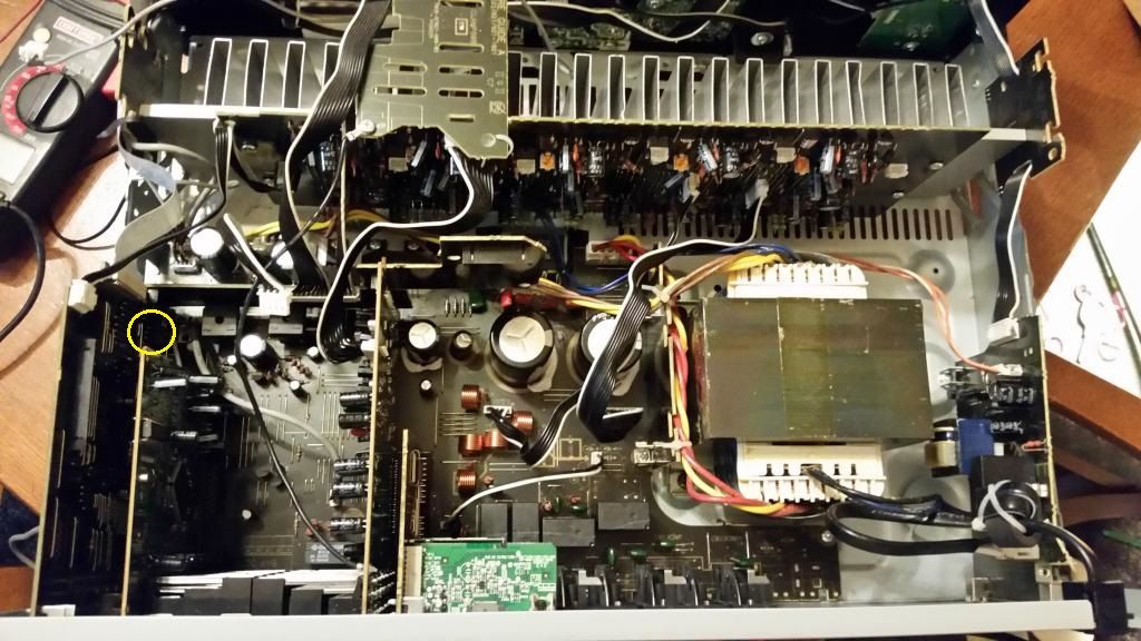
Are you able to access with your test probes the last 4 pins of CP11 at the back corner of the board (see yellow circle)?
|
|
| Back to top |
|
|
jgrice53
Joined: 10 Dec 2014
Posts: 165
Location: marion, sc 29571
|
| Link Posted: Fri Dec 19, 2014 3:51 am Post subject: |
|
|
pin 1 gound
pin 2 -31v
pin 3 1.7v
pin 4 0.0v
these measurements are with the CPU board removed, the only way i could get to the pins
|
|
| Back to top |
|
|
macgyver655
Joined: 22 Aug 2007
Posts: 8508
|
| Link Posted: Fri Dec 19, 2014 6:20 am Post subject: |
|
|
| jgrice53 wrote: | pin 1 gound
pin 2 -31v
pin 3 1.7v
pin 4 0.0v
these measurements are with the CPU board removed, the only way i could get to the pins |
What I find interesting is pin 3 at 1.7v
It should normally have @ 3.2v but it gets that power from the CPU board. So if you had the CPU board disconnected it should be zero. And looking at the main board schematics it shouldn't have the 1.7v
But we can ignore that and move on. All of the tests so far, after being corrected, lol, have been ok. So what we have left is to take some measurements on a bunch of pins on the CPU ic. It is late now so I will work up what I need in the am and post it. This should be the final test to make a determination.
What I would like you to do until then is this. Remove that jumper wire on the power supply board.
Make sure "ALL" boards are installed, "ALL" wires are connected, and "ALL" screws are in except the top cover.
Once this is done I want you to try this. Also have a pen and paper handy to write down some numbers.
With the receiver plugged in and in standby, press and hold the (Preset - and standby/on) buttons for at least 5 seconds and the display should come on with the letters "DC" and then some numbers. It will only stay on for 5 seconds so do this quick. Press enter and it should have "OVER" and some number. Press enter again and it should have "TEMP" and some numbers. Try to remember the numbers and write them down after your done. If at anytime you stop for 5 seconds and the display goes to normal then start over.
If this does work and you get the numbers I then want you to try to clear those numbers doing the following.
During standby, press and hold the (ALC/standard surr and standby/on) buttons for at least 10 seconds until the display comes on. It should say "CLEAR". Press the enter key and it should read "OK". Press enter again and it should read "BD"
If this works then go back and check the error count again and see if it was cleared.
Try turning on receiver normally.
|
|
| Back to top |
|
|
macgyver655
Joined: 22 Aug 2007
Posts: 8508
|
| Link Posted: Fri Dec 19, 2014 6:34 am Post subject: |
|
|
Oh, and if none of that works try this.
In standby mode, press and hold the (Advanced surround and standby/on) buttons for at least 3 seconds and it should turn on.
Then turn off and try to turn on again. Or if it had shut off try turning on again.
And when doing any of these button pressing procedures that involve the standby/on button, try to press the button other then the standby button slightly before the standby button just to be sure it senses that other button press before the on button press. Or it may just try to turn on in regular mode and shut back off again. But just slightly before, like 1/2 second.
|
|
| Back to top |
|
|
jgrice53
Joined: 10 Dec 2014
Posts: 165
Location: marion, sc 29571
|
| Link Posted: Fri Dec 19, 2014 3:35 pm Post subject: |
|
|
okay mac, here is what i got
temp 1 :050
temp 2 :00
over :43
after clearing the numbers
temp 1 :00
temp 2 :00
over :01
it would not turn on, so I tried standby mode, press and hold the (Advanced surround and standby/on) buttons for at least 3 seconds.
after that still no turn on. all i get is vol min for 3 sec. then off
|
|
| Back to top |
|
|
macgyver655
Joined: 22 Aug 2007
Posts: 8508
|
| Link Posted: Fri Dec 19, 2014 4:02 pm Post subject: |
|
|
Looks like even after clearing it out it set another over error. So looks like we need to test right on the CPU pins. Give me an hour to work this up.
Is it all back together?
Do you have a power strip with an on/off switch?
Resolder the wire back across that cap by the main relay.
If you have a file, file the tip of your DMM pos probe to a nice sharp point.
I'll be back shortly.
|
|
| Back to top |
|
|
jgrice53
Joined: 10 Dec 2014
Posts: 165
Location: marion, sc 29571
|
| Link Posted: Fri Dec 19, 2014 4:12 pm Post subject: |
|
|
|
okay, got it
|
|
| Back to top |
|
|
jgrice53
Joined: 10 Dec 2014
Posts: 165
Location: marion, sc 29571
|
| Link Posted: Fri Dec 19, 2014 4:12 pm Post subject: |
|
|
|
yes all back together except the cover
|
|
| Back to top |
|
|
macgyver655
Joined: 22 Aug 2007
Posts: 8508
|
| Link Posted: Fri Dec 19, 2014 6:21 pm Post subject: |
|
|
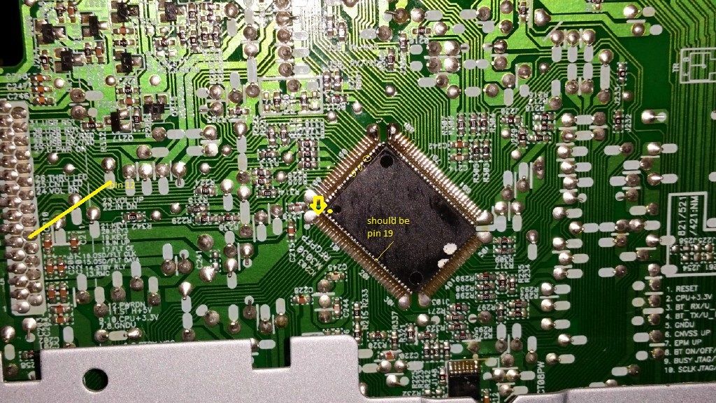
You can stand the receiver up on end so the cpu chip is easy to get at for testing. Plug in your power strip with the switch turned off and plug your receiver into that. This way you can power it up and down with the switch on the power strip. I recommend placing your probe tip on a pin first and then power it on, get your reading and power it off and then remove probe. This is less chance of slipping while testing and damaging the ic. This is where a nice sharp tip is nice. I want you to test high on the pin, right where it enters the chip. This way it is also testing the solder connection. I attached a picture as an example. Clip your neg probe right to the chassis nice and tight so it won't fall off and we end up with bad readings. Set your DMM to DC voltage and test the following pins and fill in the voltage. Don't press real hard with you probe. Just enough to make contact.
12 ____
16 ____
19 ____
21 ____
22 ____
25 ____
26 ____
27 ____
33 ____
34 ____
37 ____
38 ____
46 ____
58 ____
59 ____
60 ____
62 ____
71 ____
76 ____
81 ____
82 ____
85 ____
88 ____
90 ____
91 ____
92 ____
97 ____
98 ___
99 ____
100 ____
|
|
| Back to top |
|
|
jgrice53
Joined: 10 Dec 2014
Posts: 165
Location: marion, sc 29571
|
| Link Posted: Fri Dec 19, 2014 9:42 pm Post subject: |
|
|
12 3.2v
16 3.2v
19 2.7v
21 0v
22 0v
25 0v
26 .6v
27 0v
33 0v
34 3.2v
37 3.3v
38 3.3v
46 0v
58 0v
59 0v
60 0v
62 0v
71 0v
76 0v
81 3.2v
82 0v
85 0v
88 0v
90 0v
91 0v
92 0v
97 3.2v
98 3.2v
99 3.2v
100 0v
|
|
| Back to top |
|
|
macgyver655
Joined: 22 Aug 2007
Posts: 8508
|
| Link Posted: Fri Dec 19, 2014 10:33 pm Post subject: |
|
|
I need you to go back and recheck these pins.
62 ____
71 ____
82 ____
85 ____
90 ____
91 ____
92 ____
|
|
| Back to top |
|
|
macgyver655
Joined: 22 Aug 2007
Posts: 8508
|
| Link Posted: Fri Dec 19, 2014 10:38 pm Post subject: |
|
|
|
Hold on a sec. The schematic is different then the board image. Let me check this.
|
|
| Back to top |
|
|
macgyver655
Joined: 22 Aug 2007
Posts: 8508
|
| Link Posted: Fri Dec 19, 2014 10:48 pm Post subject: |
|
|
|
We are ok. Continue with the recheck of those pins listed.
|
|
| Back to top |
|
|
jgrice53
Joined: 10 Dec 2014
Posts: 165
Location: marion, sc 29571
|
| Link Posted: Sat Dec 20, 2014 6:41 pm Post subject: |
|
|
okay mac, after checking and double checking what i came up with is
62 0v
71 3.2v
76 3.2v
82 0v
85 0v
90 0v
91 3.2v
92 0.v
also pin 12 on the ic is 3.2v but it is 0v on the connector
|
|
| Back to top |
|
|
macgyver655
Joined: 22 Aug 2007
Posts: 8508
|
| Link Posted: Sat Dec 20, 2014 7:21 pm Post subject: |
|
|
| jgrice53 wrote: | okay mac, after checking and double checking what i came up with is
62 0v
71 3.2v
76 3.2v
82 0v
85 0v
90 0v
91 3.2v
92 0.v
also pin 12 on the ic is 3.2v but it is 0v on the connector |
With the exception of pin 82, these should all be 3.2v
So I want you to check again but this time test on the board at the solder, not high on the pin.
Pin 12 does not go to a connector so I do not know what you are looking at.
|
|
| Back to top |
|
|
jgrice53
Joined: 10 Dec 2014
Posts: 165
Location: marion, sc 29571
|
| Link Posted: Sat Dec 20, 2014 7:46 pm Post subject: |
|
|
|
in the post where you listed all the pins as well as the picture of the ic there is a yellow line drawn to pin 12. i mistakenly thought that you wanted it checked too.
|
|
| Back to top |
|
|
jgrice53
Joined: 10 Dec 2014
Posts: 165
Location: marion, sc 29571
|
| Link Posted: Sat Dec 20, 2014 7:48 pm Post subject: |
|
|
|
i am checking pins 62, 85, 90 and 92 again
|
|
| Back to top |
|
|
|
|