| View previous topic :: View next topic |
| Author |
Message |
draganm
Joined: 08 Mar 2006
Posts: 8990
Location: Colorado

|
 Link Posted: Mon Sep 29, 2014 11:54 pm Post subject: Link Posted: Mon Sep 29, 2014 11:54 pm Post subject: |
 |
|
| stridsvognen wrote: | So will someone test those new VNBs ? Or do we keep guessing about how they perform.?  |
Bryan will probably list these in the FS section, so the best person to test them is you
|
|
| Back to top |
|
 |
stridsvognen
Guest
|
| Link Posted: Tue Sep 30, 2014 5:29 pm Post subject: |
|
|
| draganm wrote: | | stridsvognen wrote: | | So will someone test those new VNBs ? Or do we keep guessing about how they perform.? |
Bryan will probably list these in the FS section, so the best person to test them is you |
Ill not be willing to pay for those boards + shipping just to test them. If anyone wants to send a set to me ill be happy to compare them to the old original neckboards.
I think MP might have a set, and know how they perform. Ill ask him when i visite him.
|
|
| Back to top |
|
|
draganm
Joined: 08 Mar 2006
Posts: 8990
Location: Colorado
|
| Link Posted: Mon Oct 13, 2014 3:55 pm Post subject: |
|
|
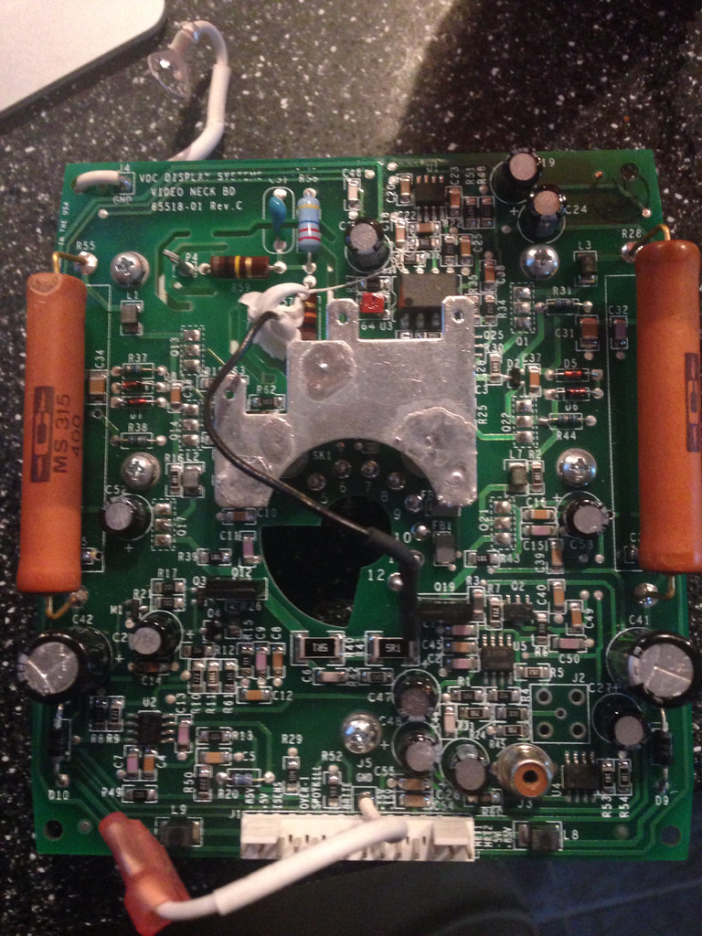
nash heard back from Scott? I'm guessing in your first pic the black wire coming off the board just above R62 is the G2 wire for p19's right? And the jumper on the back should be on B but isn't? I'm going to do a quick continuity test between that jumper location and the B-jumper tonight but it would be nice to be 100% sure.
It would be good to figure this out before someone burns a tube. I'll even do a comparison here between one of these and an original card using a basic test pattern and 8 inch tube ( as long as I don't get crucified for not using NASA test patterns burned onto brand new DVD's by nubil Virgins).
| Nashou66 wrote: | Dragan, What rev is yours I can't make out the letter.
here is mine these I believe are for DVB's and LCP's
Athanasios |
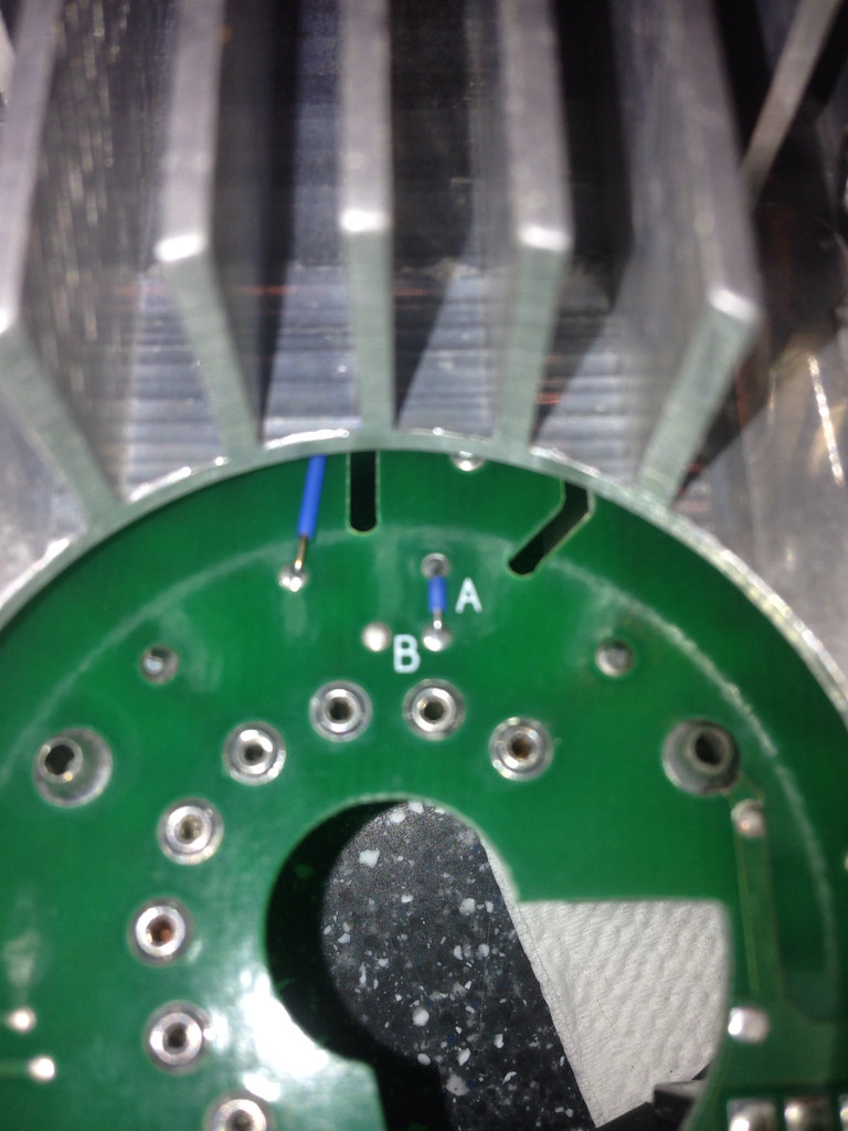
| Nashou66 wrote: | Ok mine is 81771-01 but my jumper is at location A i believe and it should not then have a G2 wire off the board, but it does? I have been e-mailing Scott lets see what he says.
 |
|
|
| Back to top |
|
|
Nashou66
Joined: 12 Jan 2007
Posts: 16171
Location: West Seneca NY
|
| Link Posted: Mon Oct 13, 2014 4:34 pm Post subject: |
|
|
He told me that the neck boards I have are for the regular 8/9 inch marquee tubes and that jumper should not be on pin A. That the wire is for a G2 at pin 2. But if the Jumper is there as on mine it is for G2 at pin 6 with no wire attached. But if you look at the pin outs for the LCP and the 8 Inch (DBV?) there is no connection at pin 6 so if the G2 goes there as well it wont harm anything I would assume.
I did a continuity test , I posted it somewhere here, but i found continuity from the end of the wire to the G2 connection on the VNB and also the resistance from the G2 connector on the VNB to pin 6 has the correct resistance of the G2 resistors as does the end of the black G2 wire.
Scott has no idea why it is like that, he never answered if it harm either tube.
Athanasios
_________________
Don't blame your underwear for your crooked ass~ unknown Greek philosopher
"Republicans believe every day is the Fourth of July, but the Democrats believe every day is April 15." --- President Reagan
One Smart Dog!!!
Marquee High Performance Bellows now shipping!!
Marquee Modifications and Performance Enhancement
Marquee C-element and Bellow removal
|
|
| Back to top |
|
|
Nashou66
Joined: 12 Jan 2007
Posts: 16171
Location: West Seneca NY
|
| Link Posted: Mon Oct 13, 2014 4:42 pm Post subject: |
|
|
Hi Nashou,
The boards can be used for tubes with G2 on pin 2 or pin 6. So for P19LCP09 you would put the jumper in the "B" position and install the G2 wire with the pin socket that you connect to pin 2 like the standard Marquee. If you have P19LUG tubes you would install jumper "A". You don't need the G2 wire for this tube.
The new boards are compatible with the VIM boards. The limitation is you cannot use the original neck cards with the new neck cards. If you want to use new neck cards you have to use three of them. If one or two original neck cards are installed the spotkill will not work on the new neck cards. Dangerous! The spotkill works fine with three new neck cards installed.
The remote control Brightness setting will have to be set a little different with the new cards as compared to the old ones and the internal test patterns won't be right.
Take care,
Scott
And
Not sure how your cards come to have the configuration that they do. Maybe Bubba has been at them? They didn't leave VDC like that. The cards can work with either the LCP or LUG tubes by adding the jumper and/or the G2 wire with the pin socket to connect to pin 2 of the tube.
Scott
And
Jumper "A" looks like it was installed at the factory. Probably someone added the G2 wire so they could use the cards with the LCP tubes. Jumper "B" connects the unused pin 6, through a resistor, to ground to keep it from picking up a static charge when the HV comes up.
Scott
Nashou
_________________
Don't blame your underwear for your crooked ass~ unknown Greek philosopher
"Republicans believe every day is the Fourth of July, but the Democrats believe every day is April 15." --- President Reagan
One Smart Dog!!!
Marquee High Performance Bellows now shipping!!
Marquee Modifications and Performance Enhancement
Marquee C-element and Bellow removal
|
|
| Back to top |
|
|
draganm
Joined: 08 Mar 2006
Posts: 8990
Location: Colorado
|
| Link Posted: Mon Oct 13, 2014 6:33 pm Post subject: |
|
|
| Nashou66 wrote: | Jumper "A" looks like it was installed at the factory. Probably someone added the G2 wire so they could use the cards with the LCP tubes. Jumper "B" connects the unused pin 6, through a resistor, to ground to keep it from picking up a static charge when the HV comes up.
Scott
Nashou |
ok thanks, that makes sense now. jumper at B does the same thing we have been doing when doing the LUG mod to an original card. You drill out the 6 pin and ground the remaining trace with a 1Kohm resistor. This keeps the unused circuit from picking up stray fields.
Like you said it will still work with jumper at A since the pin 6 is a dead end on LCP's, but now you have a open ended pin that is part of your P14 circuit just hanging out there like an antenna. 
I'll move the jumper over, make a G2 fly-wire, and test these.
now for the big question, will these work on 8" tubes ? 
|
|
| Back to top |
|
|
Nashou66
Joined: 12 Jan 2007
Posts: 16171
Location: West Seneca NY
|
| Link Posted: Mon Oct 13, 2014 11:43 pm Post subject: |
|
|
| draganm wrote: | | Nashou66 wrote: | Jumper "A" looks like it was installed at the factory. Probably someone added the G2 wire so they could use the cards with the LCP tubes. Jumper "B" connects the unused pin 6, through a resistor, to ground to keep it from picking up a static charge when the HV comes up.
Scott
Nashou |
ok thanks, that makes sense now. jumper at B does the same thing we have been doing when doing the LUG mod to an original card. You drill out the 6 pin and ground the remaining trace with a 1Kohm resistor. This keeps the unused circuit from picking up stray fields.
Like you said it will still work with jumper at A since the pin 6 is a dead end on LCP's, but now you have a open ended pin that is part of your P14 circuit just hanging out there like an antenna.
I'll move the jumper over, make a G2 fly-wire, and test these.
now for the big question, will these work on 8" tubes ? |
Actually that is more like an ARC suppressor or HV static charge run off, not an antenna . The end of the tube is
full of static charge when the HV come on. If there was no path to ground there would be lots of arcing. so Jumper "B"
now leads the static to GND . So someone on MY VNB had these possibly on an LUG then needed it for an LCP or an 8" DMV tube which has G2 on pin 2. They just never took Jumper A off and moved it to Jumper B.
Or maybe you did say that And just misinterpreted .
I should put those on my 8 inch test bed and see if it arcs, I bet they added the white silicon thinking it stop the arcing or maybe for support.
Nashou
_________________
Don't blame your underwear for your crooked ass~ unknown Greek philosopher
"Republicans believe every day is the Fourth of July, but the Democrats believe every day is April 15." --- President Reagan
One Smart Dog!!!
Marquee High Performance Bellows now shipping!!
Marquee Modifications and Performance Enhancement
Marquee C-element and Bellow removal
|
|
| Back to top |
|
|
draganm
Joined: 08 Mar 2006
Posts: 8990
Location: Colorado
|
| Link Posted: Sat Oct 18, 2014 11:11 pm Post subject: |
|
|
|
nash how is your G2 lead attached to WH2 (can you see under the white silicone blob?). On mine there is just a loop here, like a test point for clipping on a multi-meter lead. I don't want ot just solder directly to this but the other option is to pull the heat-sink off, de-solder the loop, and solder the G2 wire right ot the board
|
|
| Back to top |
|
|
Nashou66
Joined: 12 Jan 2007
Posts: 16171
Location: West Seneca NY
|
|
| Back to top |
|
|
digitalayon
Joined: 02 Mar 2009
Posts: 921
|
| Link Posted: Mon Oct 20, 2014 3:45 pm Post subject: |
|
|
|
holy crap you guys are too advanced for me with this talk.
|
|
| Back to top |
|
|
draganm
Joined: 08 Mar 2006
Posts: 8990
Location: Colorado
|
| Link Posted: Mon Oct 20, 2014 4:07 pm Post subject: |
|
|
well I took off the heat sink and removed the TP loop, soldered the G2 wire directly to the board like of the original E-home cards, moved the jumper over to B.
I plan ot test with a stock marquee card, stock VDC card, and then maybe if the VDC card is inferior I'll swap out the H1100 chip with in intersil 5166 and see what happens. This is assuming of course I can actually get a test pattern up. My POS Chinese DVD player won't even play the Joe Kane video essentials disc. My POS home theater personal computer with theater tek (remember that crap from 10 years ago) plays the disc but locks up a few seconds in for god knows what reason.
Does anyone have a simple 1080P test pattern I can download and play with windows media player? I have internet connectivity in the shop but looking on the internet for a simple high resolution test pattern is nightmare-ish.
|
|
| Back to top |
|
|
Nashou66
Joined: 12 Jan 2007
Posts: 16171
Location: West Seneca NY
|
|
| Back to top |
|
|
draganm
Joined: 08 Mar 2006
Posts: 8990
Location: Colorado
|
| Link Posted: Tue Oct 21, 2014 4:17 am Post subject: |
|
|
so this is without changing anything except convergence, red which moved quite a bit and blue which moved a little. First the new VDC design then the old factory boards. Color balance did not appear ot be change when looking at the gray scale but ?
Since these are just 8 inch tubes I went with Resolution of 1440 x 900
| Description: |
|
| Filesize: |
141.38 KB |
| Viewed: |
5995 Time(s) |

|
| Description: |
|
| Filesize: |
179.63 KB |
| Viewed: |
5995 Time(s) |

|
|
|
| Back to top |
|
|
gjaky
Joined: 05 Jun 2010
Posts: 2790
Location: Budapest, Hungary
|
| Link Posted: Tue Oct 21, 2014 6:02 am Post subject: |
|
|
It looks like the newer VNB resolves higher bandwidth... I'm surprised to see how the older VNB is lacking at 1440x900, what was the refresh?
_________________
projectors in the past : NEC 6-9PG xtra, Electrohome Marquee 6-7500, NEC XG 1351 LC ( with super modified Electrohome VNB neckboard !!!)
current: VDC Marquee 9500LC
The MOD: VNB-DB, VIM-DB
|
|
| Back to top |
|
|
draganm
Joined: 08 Mar 2006
Posts: 8990
Location: Colorado
|
| Link Posted: Tue Oct 21, 2014 3:31 pm Post subject: |
|
|
| gjaky wrote: | | It looks like the newer VNB resolves higher bandwidth... I'm surprised to see how the older VNB is lacking at 1440x900, what was the refresh? |
60hz, I don't have a choice on my old HTPC graphics card which is on an AGP slot.
Please tell me why you think the first picture is showing better resolution? I thought the second pic was sharper?
|
|
| Back to top |
|
|
gjaky
Joined: 05 Jun 2010
Posts: 2790
Location: Budapest, Hungary
|
| Link Posted: Tue Oct 21, 2014 6:31 pm Post subject: |
|
|
| draganm wrote: | | gjaky wrote: | | It looks like the newer VNB resolves higher bandwidth... I'm surprised to see how the older VNB is lacking at 1440x900, what was the refresh? |
60hz, I don't have a choice on my old HTPC graphics card which is on an AGP slot.
Please tell me why you think the first picture is showing better resolution? I thought the second pic was sharper? |
Evaluating bandwidth isn't about "sharpness" as you first think. The key is to compare the horizontal and vertical line sets in brightness. The horizontal lines are only limited by the focus and astig, while the vertical lines are limited by these plus the bandwidth limitation. Poor bandwidth will result in lower light output at 1:1 pixels, because the signal transition lags. In real life this really looks like a blurring effect that only washes the image in the horizontal plane. With unlimited (and flat) bandwidth the horizontal and vertical 1:1 lines would be exactly the same. This never happening but if the bandwidth is high enough we are unable to sense the difference between the vertical and horizontal line sets.
When we see color shifting or brightness difference between the two line sets that meaning bandwidth problems (because that's the only difference between them in the "display chain", assuming the astigmatism and focus are set evenly and are correct of course). And it should be noted here that the resolution of the optical system or the beam size have no importance here. With overlapped scanlines the difference is easier to see actually.
I myself like the single color (eg. green) evaluation more as it isn't depending on actual convergence yet easy to see.
I see on the pictures that with the new board there was no color shifting, but with the older yes.
_________________
projectors in the past : NEC 6-9PG xtra, Electrohome Marquee 6-7500, NEC XG 1351 LC ( with super modified Electrohome VNB neckboard !!!)
current: VDC Marquee 9500LC
The MOD: VNB-DB, VIM-DB
|
|
| Back to top |
|
|
draganm
Joined: 08 Mar 2006
Posts: 8990
Location: Colorado
|
| Link Posted: Wed Oct 22, 2014 12:19 am Post subject: |
|
|
|
ok thanks, I'll run it again tonight with green only
|
|
| Back to top |
|
|
stridsvognen
Guest
|
| Link Posted: Wed Oct 22, 2014 12:59 pm Post subject: |
|
|
Try run those new vnbs different bandwidth, and see if they have a linear response to the 1:1.
Ill bet they are peaked up. As the vim wont pass that bandwidth performance shown on that screenshot.
Lets know what pixel clock your running for these tests please.
|
|
| Back to top |
|
|
draganm
Joined: 08 Mar 2006
Posts: 8990
Location: Colorado
|
| Link Posted: Wed Oct 22, 2014 2:50 pm Post subject: |
|
|
| stridsvognen wrote: | Try run those new vnbs different bandwidth, and see if they have a linear response to the 1:1.
Ill bet they are peaked up. As the vim wont pass that bandwidth performance shown on that screenshot.
Lets know what pixel clock your running for these tests please. |
I'll try some different resolutions ASAP on a green only screen. Thinking back 2 nights ago, I'm not even sure I had the shop lights off when I tested the VDC boards at the end of the night.
AFA pixel clock, I just want to stress I'm an enthusiast, not some ISF certified super calibrator with an AV laboratory at my disposal. I can post resolutions and refesh rates, those available on my Radeon saphire video card
|
|
| Back to top |
|
|
stridsvognen
Guest
|
| Link Posted: Wed Oct 22, 2014 4:38 pm Post subject: |
|
|
| draganm wrote: | | stridsvognen wrote: | Try run those new vnbs different bandwidth, and see if they have a linear response to the 1:1.
Ill bet they are peaked up. As the vim wont pass that bandwidth performance shown on that screenshot.
Lets know what pixel clock your running for these tests please. |
I'll try some different resolutions ASAP on a green only screen. Thinking back 2 nights ago, I'm not even sure I had the shop lights off when I tested the VDC boards at the end of the night.
AFA pixel clock, I just want to stress I'm an enthusiast, not some ISF certified super calibrator with an AV laboratory at my disposal. I can post resolutions and refesh rates, those available on my Radeon saphire video card |
All you need is the HD Basic blu ray disc and run the SMPTE pattern with different framerates, it also have a 720p SMPTE pattern so you can check if it peaking feeding it 100mhz.
This kind of bandwidth testing is super low tech, a 7 year old scool girl will be able to do it
|
|
| Back to top |
|
|
|
|


