| View previous topic :: View next topic |
| Author |
Message |
macgyver655
Joined: 22 Aug 2007
Posts: 8508

|
 Link Posted: Sun Jan 17, 2010 7:21 pm Post subject: Link Posted: Sun Jan 17, 2010 7:21 pm Post subject: |
 |
|
|
At this point its up to the poster as to what he wants to do. I'm not going to debate this any further. It should really be done by a licensed electrician.
|
|
| Back to top |
|
 |
Nashou66
Joined: 12 Jan 2007
Posts: 16171
Location: West Seneca NY
|
| Link Posted: Sun Jan 17, 2010 7:32 pm Post subject: |
|
|
| macgyver655 wrote: | | At this point its up to the poster as to what he wants to do. I'm not going to debate this any further. It should really be done by a licensed electrician. |
I agree, and mine works great the way i have it thanks to Bobs instructions. I wasn't debating it, Just want to make sure i have it hooked up properly, Bob has lots of experience with these in medical field and how they install them.
Mine is wired in parallel and I don't plan a 240 volt device.
maybe Love bone should wait for Bob to also post, his is different than mine , Mine had a neater interface for connection as well which made the installation go smooth.
Hope it hooks up ok and you get rid of your hum.
Athanasios
_________________
Don't blame your underwear for your crooked ass~ unknown Greek philosopher
"Republicans believe every day is the Fourth of July, but the Democrats believe every day is April 15." --- President Reagan
One Smart Dog!!!
Marquee High Performance Bellows now shipping!!
Marquee Modifications and Performance Enhancement
Marquee C-element and Bellow removal
|
|
| Back to top |
|
|
macgyver655
Joined: 22 Aug 2007
Posts: 8508
|
| Link Posted: Sun Jan 17, 2010 7:51 pm Post subject: |
|
|
Here's a document on isolation transformer wiring. Ignore the input side since its different but the output side would be the same. Also note the diagram at the bottom which indicates the 30a breakers on the 240v side and 20a breakers on the 120v side. Also note that the diagram at the upper left which would indicate wiring for a panel box. I tried to find a diagram with the same input voltages but couldn't find one but the input voltage difference still doesn't matter for the output side voltages. It is the same.
http://www.apcmedia.com/salestools/BYSN-76ZCUG_R0_EN.pdf
|
|
| Back to top |
|
|
lovebohn
Joined: 16 Mar 2006
Posts: 181
Location: Wisconsin
|
| Link Posted: Sun Jan 17, 2010 8:14 pm Post subject: |
|
|
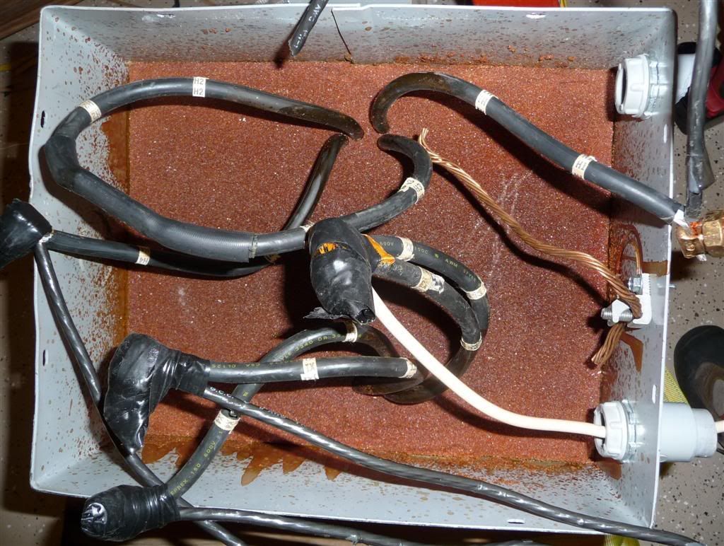
Here is a snap shot of how this was wired. Looks just like I would have guessed. These are all 6 awg wires.
input
H1 power
H4 power
H2 & H3 combined
ground wire on case
output
X1 power
X4 power
X2 & X3 combined, but neutral coming off
|
|
| Back to top |
|
|
lovebohn
Joined: 16 Mar 2006
Posts: 181
Location: Wisconsin
|
| Link Posted: Sun Jan 17, 2010 8:23 pm Post subject: |
|
|
|
I'm going to hold tight and see what Bob has to say. I see no need for running 240 output from this sub panel so either route looks to work. I do have an cert electrician in the family i could call to.
|
|
| Back to top |
|
|
Nashou66
Joined: 12 Jan 2007
Posts: 16171
Location: West Seneca NY
|
| Link Posted: Sun Jan 17, 2010 8:31 pm Post subject: |
|
|
See, yours is not specifically made for Isolation only, it is also a distribution trasformer. So to use it as an Isolation Transformer i would not go with the third wire out from the combined x2,x3. Id only use the X1 and X4 and jumper that in the panel box. the way they had it was to distributed two line voltages, a 120 volt side and a 240 volt side. you only need 120 and need to isolate the ground.
Athanasios
_________________
Don't blame your underwear for your crooked ass~ unknown Greek philosopher
"Republicans believe every day is the Fourth of July, but the Democrats believe every day is April 15." --- President Reagan
One Smart Dog!!!
Marquee High Performance Bellows now shipping!!
Marquee Modifications and Performance Enhancement
Marquee C-element and Bellow removal
|
|
| Back to top |
|
|
macgyver655
Joined: 22 Aug 2007
Posts: 8508
|
| Link Posted: Sun Jan 17, 2010 9:48 pm Post subject: |
|
|
| Nashou66 wrote: | See, yours is not specifically made for Isolation only, it is also a distribution trasformer. So to use it as an Isolation Transformer i would not go with the third wire out from the combined x2,x3. Id only use the X1 and X4 and jumper that in the panel box. the way they had it was to distributed two line voltages, a 120 volt side and a 240 volt side. you only need 120 and need to isolate the ground.
Athanasios |
Say WHAT??
|
|
| Back to top |
|
|
macgyver655
Joined: 22 Aug 2007
Posts: 8508
|
| Link Posted: Sun Jan 17, 2010 9:51 pm Post subject: |
|
|
| Nashou66 wrote: | See, yours is not specifically made for Isolation only, it is also a distribution trasformer. So to use it as an Isolation Transformer i would not go with the third wire out from the combined x2,x3. Id only use the X1 and X4 and jumper that in the panel box. the way they had it was to distributed two line voltages, a 120 volt side and a 240 volt side. you only need 120 and need to isolate the ground.
Athanasios |
This is entirely incorrect. I'm not saying anymore. You guys are going to start a fire.
|
|
| Back to top |
|
|
Nashou66
Joined: 12 Jan 2007
Posts: 16171
Location: West Seneca NY
|
|
| Back to top |
|
|
macgyver655
Joined: 22 Aug 2007
Posts: 8508
|
| Link Posted: Sun Jan 17, 2010 10:30 pm Post subject: |
|
|
| Nashou66 wrote: | Ok, I must be missing something then Mac. the layout of his transformer is different than mine but not by much, I think mine has a few more windings on the primary side.
Can you look over Bob,s instruction for my transformer and tell me if its ok? i don't want a fire 
http://www.curtpalme.com/forum/viewtopic.php?p=134279#134279
Athanasios |
Let me explain. I'm not trying to be a dick here.
I have a lot of experience in house electricity. I have installed main entrance service, wired new construction, rewired old construction along with appliance installs and appliance repair.
One thing I have always done before beginning is check with NEC and local codes. So I have been involved with electrical coding. I also know that coding can sometimes change by location but usually stricter.
So here's the issues. Call your local code enforcement officer and ask if its acceptable to jump a 120v sub panel feed from 1 hot buss to another hot buss. I'm sure I know what the answer will be.
Then call your home owners ins company and ask what the liability would be in the event of electrical or fire damage from incorrect wiring as per code.
Also I never take someone else's word for something. I check with code.
|
|
| Back to top |
|
|
Boilermaker
Joined: 21 May 2006
Posts: 527
|
| Link Posted: Mon Jan 18, 2010 1:11 am Post subject: |
|
|
Lovebohn,
This xfrm can be configured either for a 120v secondary or a 240v secondary, depending on whether the secondaries are wired in series or parallel. While either would work, I recommend the parallel 120v configuration, so:
1 - Bond the H3 & H2 primary cables together just as the picture you took. Nothing else connects to these leads.
2 - Using a 2-pole 240v breaker from your main panel, connect one of the two wires to H1 and the other to H4. Unless you have a long distance, #10 with a 2-pole 30amp breaker should be adequate. A 10kva transformer does not consume 10kva, as it only consumes what the connected load is plus a few percent for inefficiency. The circuit breaker should be sized to protect the wire, not the transformer.
3 - For 120 configuration we want the secondary windings in parallel and in phase, so bond together X2 with X4 and also X3 with X1..
4 - Unless you have a long cable run, use two #6 wires to run from the X4/X2 bond and the X3/X1 bond to feed you isolated subpanel. I assumed you will never need a 240v service from this panel. We use the larger guage because the secondary is at 120v.
5 - Connect one of these two wires (either one) to the neutral bar in your subpanel (the one that all the white wires are connected to).
6 - Connect the other wire to BOTH hot buss bars in you subpanel. You can just jumper from one to the other.
7 - If your subpanel shares a common neutral and ground buss, you must separate them or you will have done all this for nothing.
8 - Now run a ground wire from your main service panel to your xfmr and on to your subpanel. At the xfmr, there is probably a chassis ground screw you can use, and at the subpanel use the ground buss that all the bare ground wires attach to.
As far as the circuits you asked about in your pm, I recommend you not use the following:
1 - Your lighting control system - Most dimmers use some sort of pwm that can really get pretty noisey.
2 - Your bathroom circuit - code probably requires you to use a GFI type breaker which not only is not campatible with an isolated power system, but will not work.
Try it out.
Bob
|
|
| Back to top |
|
|
macgyver655
Joined: 22 Aug 2007
Posts: 8508
|
| Link Posted: Mon Jan 18, 2010 1:18 am Post subject: |
|
|
|
Man, am I glad I'm out of this one.
|
|
| Back to top |
|
|
lovebohn
Joined: 16 Mar 2006
Posts: 181
Location: Wisconsin
|
| Link Posted: Mon Jan 18, 2010 4:25 am Post subject: |
|
|
Bob,
I pulled the bathroom circuit off the sub panel last night, but don't really have any room left in the main panel so I have to keep the HT lights on the sub. If i totally pull the lights off the sub panel just as a test run before wiring the xfrm and still have the hum can i assume this shouldn't be an issue.
What is the big benefit of running 120 vs 240 output to the sub panel?
Thanks guys for all of the input, it always keeps a guy thinking. I truly appreciate the help.
|
|
| Back to top |
|
|
Boilermaker
Joined: 21 May 2006
Posts: 527
|
| Link Posted: Mon Jan 18, 2010 9:23 am Post subject: |
|
|
Lovebohn,
| Quote: | | If i totally pull the lights off the sub panel just as a test run before wiring the xfrm and still have the hum can i assume this shouldn't be an issue. |
Actually if there is a problem, it probably won't be a hum. It will be a "whistle" that changes frequency as you change dimmer setting. If there is no problem, then no harm=no foul.
| Quote: | | What is the big benefit of running 120 vs 240 output to the sub panel? |
It is not a big advantage, but it is the same advantage that you have when all circuits that feed your equipment are fed from the same "leg". It eliminates any unbalance in voltage and it also represents a perfect balance to your main panel.
Bob
|
|
| Back to top |
|
|
lovebohn
Joined: 16 Mar 2006
Posts: 181
Location: Wisconsin
|
| Link Posted: Mon Jan 18, 2010 2:38 pm Post subject: |
|
|
| Boilermaker wrote: | Lovebohn,
| Quote: | | If i totally pull the lights off the sub panel just as a test run before wiring the xfrm and still have the hum can i assume this shouldn't be an issue. |
Actually if there is a problem, it probably won't be a hum. It will be a "whistle" that changes frequency as you change dimmer setting. If there is no problem, then no harm=no foul.
| Quote: | | What is the big benefit of running 120 vs 240 output to the sub panel? |
It is not a big advantage, but it is the same advantage that you have when all circuits that feed your equipment are fed from the same "leg". It eliminates any unbalance in voltage and it also represents a perfect balance to your main panel.
Bob |
Here is the issue with the dimmer, let me know if you think it's the source or just part of the problem. If i have the dimmer off i have a hum but not as loud. If i kill power to the dimmer the hum is still there about the same as when its turned off. If i have the dimmer on (lights on) the hum is louder and if change to a different scene and have the zones dim or brighten the hum changes frequency like you describe above. All of the lights in the room are IC or little halogen, no CFL lights which the dimmer does not work well with.
Here is how the dimmer is wired.
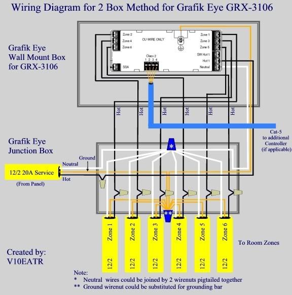
|
|
| Back to top |
|
|
Boilermaker
Joined: 21 May 2006
Posts: 527
|
| Link Posted: Mon Jan 18, 2010 5:17 pm Post subject: |
|
|
First, I will assume you have not yet installed your iso. xfmr., so the problem you just described is with normal power fed from your sub panel.
If this is correct, turn off the 20A breaker feeding your Grafix Eye panel. Then, at the sub panel carefully remove the ground wire from the ground bar for this circuit. Now, using a VOM, measure the resistance between neutral and this ground wire. You may need to use the highest setting on your VOM. What did you measure?
Now, with the ground wire still disconnected, switch your VOM to AC volts at the lowest setting, switch the breaker back on, and measure the voltage between this disconnected ground wire and the neutral buss. What did you measure?
Bob
|
|
| Back to top |
|
|
lovebohn
Joined: 16 Mar 2006
Posts: 181
Location: Wisconsin
|
| Link Posted: Mon Jan 18, 2010 5:30 pm Post subject: |
|
|
Correct, I still have the sub panel and did not have the transformer connected. I have most everything else torn apart though. I might be able to test this tonight, it might be Tuesday night before I have an answer.
Just on a real basic electrical wiring design, is there anything wrong with how my current sub panel is wired?
I have a two pole 50 amp breaker feeding the sub panel. Each hot wire goes from the breaker to the sub panel and then I also have a neutral/ground wire going from the main panels neutral/ground bus bar to the neutral/ground bus bar on the sub panel. All outlets and lights feed the hot to the 20 amp twin breakers (sub panel) which have all of the neutral and grounds going back to the neutral/ground bus bar in the sub panel. This doesn't seem like its wrong The sub panel has no ground screwed to the tin box, but the bus bars should also be doing the same thing correct?
|
|
| Back to top |
|
|
Boilermaker
Joined: 21 May 2006
Posts: 527
|
| Link Posted: Mon Jan 18, 2010 6:01 pm Post subject: |
|
|
Lovebohn,
| Quote: | | This doesn't seem like its wrong The sub panel has no ground screwed to the tin box, but the bus bars should also be doing the same thing correct? |
Yes.
|
|
| Back to top |
|
|
lovebohn
Joined: 16 Mar 2006
Posts: 181
Location: Wisconsin
|
| Link Posted: Mon Jan 18, 2010 6:58 pm Post subject: |
|
|
Bob if i run the transformer the way you recommend do I need to increase the wire size coming from it to the sub panel. I assume it could draw the complete 10kva from the one feed which 6 awg might get a little warm vs splitting the draw on 240v from the two feeds?
I love overkill on my projects.
|
|
| Back to top |
|
|
Boilermaker
Joined: 21 May 2006
Posts: 527
|
| Link Posted: Mon Jan 18, 2010 7:34 pm Post subject: |
|
|
Lovebohn,
| Quote: | | Bob if i run the transformer the way you recommend do I need to increase the wire size coming from it to the sub panel. I assume it could draw the complete 10kva from the one feed which 6 awg might get a little warm vs splitting the draw on 240v from the two feeds? |
From the load you decribed, #6 is plenty adequate - Is there a main breaker on the subpanel?
Unless your subpanel has two separate grounding buss' you will have two options. Either you can cut (split) the one you have, or you can just add another one that you can buy at any local electrical supply store. One of the two MUST be electrically isolated from the panel box. If you buy one, just get it with insulated mounting standoffs - this one will be your new neutral.
Bob
|
|
| Back to top |
|
|
|
|


